Cyclone Owners - post your reviews/comments/tips here

gear selection is a compromise between keeping motor rpm up, and leg rpm in your useabole range;

The lowest gear your legs can handle. an inexpensive watt meter wold be helpful here.

my opinion.

d

cyclone owner.
 
deardancer3 said:
gear selection is a compromise between keeping motor rpm up, and leg rpm in your useable range;

The lowest gear your legs can handle.

d

.......Which is exaggerated more when powering the planetary equipped motors with 36VDC>48VDC rather than the manufacturer designed/intended 24VDC.

Best compromise loaded RPM @ 24V = ~2500RPM which when geared down to the cranks = (2500RPM/(9.33 x (44/14))) = 85RPM best motor-complimenting pedal cadence [toward the faster end of comfort for most cyclists, but still acceptable]

......So you can see the problem at higher voltages in which best compromise motor RPM is ~3250RPM@36VDC and ~4165RPM@48VDC (a bit slower than the additional increased voltage ratio might suggest).

At these higher voltages, this equates to a best complimentry pedal cadence of ~110RPM @36VDC and ~142RPM@48VDC. Clearly these are uncomfortably fast and unachievable by most riders, especially owners who added a motor assist to their bicycle specifically to reduce the amount of pedal effort required. Also, unless your a cycling athlete, human pedal power is less efficient at those sort of ridiculously fast cadences. Much better to reduce leg RPM and add more torque per stroke.

So what can the 36V/48V planetary equipped cyclone motor owner do other than putting up with the standard kit's flaws?

One of the simplest mods for owners of twin chain/triple chainwheel kits is swapping out the 44T motor driven chainring for something of much higher tooth count.
Say you swap the 44T chainring for a 60T. That takes ideal motor speed matching pedal cadence from 110RPM>81RPM@36VDC and 142RPM>104RPM@48VDC. You could go even higher chainring tooth counts if possible. The main limitations would be ground clearance, frame clearance and aesthetics. Unfortuanately 14T is the lowest tooth count freewheel i know of that fits on a 30mm Dia/1mmT BMX freewheel adapter as used on the output shaft on the cyclone planetary gearbox. So reducing the driving gear is not an option.

Yes you probably need to get a custom chainring made when chasing these sort of ridiculously high tooth counts whilst still matching the MTB 110BCD that the standard FW crank setup uses.
These guys would custom make what you need; http://www.cycleunderground.com.au/chainringdesigns.htm (They do offer higher tooth counts than what the webpage suggests)
[Im sure there are other custom chainring manufacturers out there that im not aware of]

Short of adding a second reduction stage via a jackshaft [much more difficult, less efficient] then this is my first recommendation trying to reduce the 36V/48V kit pedal assist limitation.
 
boostjuice said:
Short of adding a second reduction stage via a jackshaft [much more difficult, less efficient] then this is my first recommendation trying to reduce the 36V/48V kit pedal assist limitation.
A smaller pitch chain would be the next step, I guess. It would need a custom motor freewheel and chainring adaptor, though.
 
Hi, I do not own or use a Cyclone motor, but I do have 2 ebikes. I have found that digital meters can give a fault reading if they do not pull a load. if digital meter states 26v no load and 13 under load, I have found my electric problems are often a bad/poor connection between the batteries. I normally test this hot using a piece of heavy wire with a hd alligator clip on each end. while under light load, jumper each single wire one at a time at the mechanical connection.[not the inside of the connector] if the jumper make any difference at all, the wire you jumped is bad or one of two ends are bad. I have also found unsoldered crimp connectors are normally the weak point. For this reason I have stopped using them. I'm sure you have thought of this, but being that I'm new at this and did see a post, I wanted to toss the idea out there.... good luck!
 
I read boosts previous posts on this problem in another thread too with interest. I have a couple of questions now.

What does the 9.33 relate to? With your formula If I swap out the 14 for a 13. I get down to 102 (3250/(9.33 x (44/13) So a 60 tooth front with a 13 front would give 75 rpm. A very comfortable cadence. Am I trying to get to this in top gear at full throttle or is 3/4 better...
Would it be better to achieve this in 5th of my 8 ring rear, and suffer loses in efficiency in the last 3 higher gears & use less throttle & more peddle power. :? How much extra amp draw & loss of motor efficiency is there running at say = (44/14) at a cadence of 80 to 85.Sorry for all the questions :D

I have the felling this is a "how long is a bit of string" series of questions on my part :lol: & the answer is going to be "too many variables for an ideal" kind of answer.

I'm also wondering why bother with the smaller front crank at all, I have not used it yet even on a 10 degree incline. :?
I do know I need a cycle analyst of watts meter to help me get the best out this setup.
 
graemebc said:
I read boosts previous posts on this problem in another thread too with interest. I have a couple of questions now.

What does the 9.33 relate to? planetary gearbox reduction With your formula If I swap out the 14 for a 13. I get down to 102 (3250/(9.33 x (44/13) So a 60 tooth front with a 13 front would give 75 rpm. A very comfortable cadence. Yes the 14T>13T mod will also help. Whether it's cost is worth it in addition to a larger chainring is up to you. Am I trying to get to this in top gear at full throttle or is 3/4 better... The standard Cyclone throttle is setup as a speed controller (like most) rather than a IMHO more intuitive current controller (possible to convert the signal from speed>current control using a Cycle Analyst >=2.11, Well worth it :wink:). They also suffer from poor low speed control [Which is rectified with some aditional resistors spliced into the cable] http://www.endless-sphere.com/forums/viewtopic.php?f=2&t=12775
Anyway, point is a certain throttle position will equate to the steady state speed of your best compromise RPM once acceleration/deceleration is complete. A CA is really needed to find this throttle position. when you have found it and you get used to the 'feel' of your assisting pedal cadence that matches this, you be able to more consistantly optimise your efficiency. Of course there is an optimal point, but you are really just trying to stay near it rather than right on it all the time. The problem is that the standard 36>48V kit's gearing doesn't even allow you to get close.


Would it be better to achieve this in 5th of my 8 ring rear, and suffer loses in efficiency in the last 3 higher gears & use less throttle & more peddle power. :? Not sure what you mean here How much extra amp draw & loss of motor efficiency is there running at say = (44/14) at a cadence of 80 to 85. Depends on loading (gradient), battery voltage, how much power you're adding with your legs etc.Sorry for all the questions :D

I have the felling this is a "how long is a bit of string" series of questions on my part :lol: & the answer is going to be "too many variables for an ideal" kind of answer.

I'm also wondering why bother with the smaller front crank at all, I have not used it yet even on a 10 degree incline. :? It's there in case you have motor troubles or run out of battery power - Easier to lug the weight up hills as you 'crawl' home.
I do know I need a cycle analyst of watts meter to help me get the best out this setup. Yep.
 
Hi Folks - I'm interested to know how the Cyclone 3 chainring system would work with the dual freewheel BB system I designed. See http://endless-sphere.com/forums/viewtopic.php?f=28&t=15529. I got most of the parts I used on the prototype from SickBikeParts but the concept should be compatible with the Cyclone system. Moving the freewheel from the motor to the sprocket on the BB spindle means you could use a smaller motor sprocket. Using boost's formula with a 9T on the motor and a 48T on the BB, 24V would be 50 rpm, 36V - 65rpm and 48V - 84rpm. Using a 48T crank sprocket and 11T as the highest rear gear on a 26" mtb gives 17 mph at 24V, 22 mph at 36V and 28.4 mph at 48V. Going to a 44T as the motor-driven sprocket, the 48V cadence goes to 91.3 and the top speed to 30.7. (Bike Analyzer http://www.arachnoid.com/bike/ numbers).

I'd be happy to work with people to adapt the system. PM me or reply back here if you are interested - jd
 
Yes indeed, your dual freewheel crank setup would make easier the ability to gain increased/adequate gear reduction to the cranks. However, IMHO 1/2" pitch bicycle sprockets less than ~12>14T make too much noise for most peoples liking at even moderate - post planetary- reduction speeds (chordal effect). A swap to one of the smaller pitched chain standards such as #25 or #219 would likely be a better compromise as far as noise and efficiency are concerned. By changing to this, the increased tooth count for a given smaller diameter driving sprocket would add a negligible increase in noise compared with 1/2" pitch chain.
Regardless of whether you changed chain/sprocket standards or not, one point to keep in mind is the fact that the output shaft of the planetary gearbox is 20mm in diameter. This is going to limit the smallest diameter of the driving sprocket possible if using the most easily adapted keyed-bore mounting method to match the Cyclone OP shaft. There has to be enough material/wall thickness left between the bore and the tooth profile to ensure strength.....

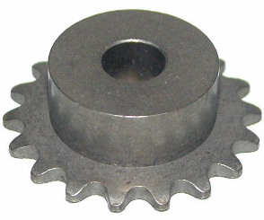
To gain similar reduction as a 9T>44T 1/2" pitch chain setup, you could use a 18T>90T #25 pitch chain setup - similar overall diameters. Unless you were able to source an 18T #25 20mm keyed bore sprocket off-the-shelf, you would have to get one bored out and a keyway broached to match the Cyclone 20mm OP shaft. All the ones i have ever found online have imperial round bore diameters with setscrew locking, or are D-bore profile.

90T #25 sprocket - adaptable to a freewheel http://www.monsterscooterparts.com/90-tooth-25-chain-sprocket-schwinn-izip-mongoose-gt-scooters.html
yhst-92821211804676_2087_2652580

18T #25 sprocket - enough material to bore out to 20mm and add a keyway http://www.electricscooterparts.com/sprockets.html
SPR-2518C.jpg


http://www.evdeals.com/Gearing.htm advertise that they can produce custom sprockets which may mean they would take on the task of matching the large sprocket to mount on a freewheel. They may also be able to machine the bore of a smaller sprocket to the profile of the Cyclone OP shaft...
 
Thanks for the response juice. The next question I have is: can the the Cyclone motor or mount be shifted to the left enough to maintain chain alignment? My design requires the motor-driven sprocket to be the inboard one, toward the midline, with the outboard crank-driven sprocket powering the main chain. I fabricated my own motor mount and attached it to the downtube inside the triangle but it might not be very cost-effective to buy the Cyclone kit and then throw away the motor FW, chain, sprockets, motor mount, etc and have a bunch of parts fabricated. It looks like you can buy motors and misc parts separately from the Cyclone site, so maybe it would work, especially if it got you exactly what you wanted in an ebike...jd
 
I would be willing to be a guinea pig to find out if you could make this work on a cyclone. :) I'm well interested in seeing what's possible with this design. I'm not so sure about the width moving it even further to the left however. You would need to move the motor up the frame out the arc of the peddle on the left hand side. Longer chain etc & redoing the motor mounting bolts to move it further inboard would be relativity simple though.
 
.....Actually, scrap the idea of using #25 chain. It's tensile strength is far too low for the force-tension at work in crank driving reductions. It's really only useful for transfering decent power under higher RPM, lower force-tension conditions.

#25 1/4" pitch chain--------------- Tensile strength = ~781 lb (354 kg)----------Recommended max working load = ~140 lb (64 kg)
#40 1/2" pitch (Bicycle chain) ----Tensile strength = ~3,125 lb (1,417 kg)------Recommended max working load = ~810 lb (370 kg)
http://en.wikipedia.org/wiki/Roller_chain
#219 0.306" pitch Go-Kart chain-----------------Tensile strength = ~2200 lb (998 kg)

That leaves #219 chain as one of the few small pitch chain types capable of the force-tension required.

This thread should guide you to the parts you need http://endless-sphere.com/forums/viewtopic.php?f=28&t=12677&start=0
 
That looks good, boost. Graemebc, I'll PM you with more details of how I did things later today. Gotta go to work now - jd
 
Back
Top