demo 8 astro 3220

recumpence said:
One possibility;

If the battery blew out under load, it can damage the controller. It is not common, but it is a know issue. This is why controllers should not have a fuse between the battery and the controller.

Matt

thanks Matt, all i have between the batteries and controller is a 200amp shunt and battery isolator switch no fuse or do you mean i should have a fuse? i know it's hard to know but is there any other thing that could case the battery to fail and lose voltage as in any other thing i have done? something with my drive or motor? one other thing with my motor when i took the back cover of to machine cooling holes one of the copper wires within one of the three wire's had cracked i contacted astro and they told me to just re solder it together which i did could this cause a issue? i dont think so but not sure.

the batteries both charged up fine and i did a couple of runs unloaded before i went for a ride. i also took the controller apart and nothing looks burnt only a little black on the white wire? or maybe i just disconnected in time.

i have to admit it was quite disappointing after spending about a year building this bike for it to only last 30 seconds doesnt give me alot of faith in this system, but if it was just a rare battery failure maybe it will be a one off for me. i have contacted castle creations about repair but i guess i will have to send back to usa for repair which with me being in Australia may take a while.

also matt one question i have, with my unloaded tests the motor felt quite responsive as in there was a lot of range with the throttle if that makes sense. But from what i have read these type of systems only like to go flat out, does that mean that you cant run these systems at low speeds? or 1/4 or 1/2 throttle? do you have to go flat out? because like you said this bike will be a wheelie monster and in the short ride i had i reckon if i went full throttle the bike would have flipped!

thanks for all your help, just hopefully i can get the motivation to keep going with this project.
 
The issue with a fuse is if the fuse blows while under heavy load, the FETs in the controller can blow from the huge spike that occurs under those conditions.

When people talk about these systems running best at full throttle, they are referring to the heavy load the FETs in the controller sees at partial throttle. Basically, of you pull 100 amps from the battery at 50% throttle, the controller FETs see short bursts of 200 amps. If you pull 100 amps at 25% throttle, the FETs will actually see short bursts of 400 amps! So, you can run low throttle. But, low throttle at very high amp loading is hard on the controller.

Matt
 
thanks matt for clearing up about the fuse and the throttle. I still find all the electronic side confusing as if the controller is rated to 160 amps, how can the controller last if the FETs see burst of 200 amps and 400amps! isnt anything over 160amps going to kill the ESC or is the 160 just the input max amps from the battery.

also i am being sent a new battery from hobby king under warranty and i sent the controller of to Castle today for repair, so i should be able to try again in about a month once i get the controller again.

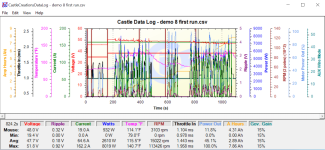
i also sent a Email to castle about what happened and after many emails from Bernie Wolfard from castle he reckons that voltage ripple killed the ESC even though i have extra Caps, but he also told me that inadequate batteries are the biggest killer of ESC and caps are only cheap insurance for failing batteries? But if it is inadequate batteries doesn't that mean that you where right Matt? as in the battery failed. and all you guys seem to be running extra caps with great success.

also once i get it back i am reluctant to try it again with the same set up as i dont want to have another failure straight away, i know i am pushing it to run it thru the gears but can someone check if i have worked this out correct.

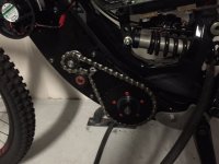
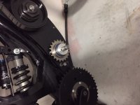
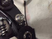
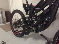
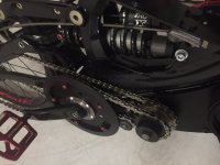
this is the current set up,

astro 4T max rpm 8100 and 5.2nm of torque

1st reduction 4:1 (2028rpm and 20.8nm)
2nd reduction 4.8:1 (422rpm and 99.8nm)
3rd reduction to crank 2.75:1 ( 153rpm and 275nm! )
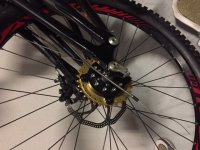
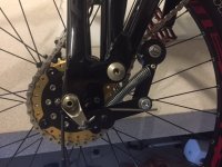
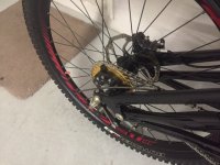
then to 26" wheel

could this be to much reduction and torque? ( i know you guys have told me this already, but isnt this what motomoto's i think his name was roughly did?)

next two ideas straight from freewheel to back 26in wheel so bypassing the crank reduction

1st idea is to run chain straight from BMX freewheel to rear wheel so it would be 1st and second stay the same 422rpm 99.8nm only two reductions

2nd idea 1st reduction 4:1 but change second reduction to 2.4:1 making it 845rpm 50nm at freewheel then chain to rear wheel

would the above two be easier on the controller being more rpm but less torque? that is if i have worked it out right.

sorry for all the questions but just trying to get it right for round two.

also copy of last email from castle creations below

Daniel,

You cannot have too much capacitance on the input leads as long as they are ultra-low ESC aluminum electrolytics. Other types of Ultra-Low ESR caps will work with tantalums seeming the obvious choice. However, the owner of Castle Creations started designing real aviation electronics where tantalums are banned because if they get overloaded they explode which is not an acceptable failure state in an airplane carrying people. The best would be ultra-low ESR ceramic caps but these are simply too expensive for production work.

The gotcha here is you cannot depend on capacitance to make up for inadequate batteries. The reason we sell cap packs is for cheap insurance against a failing batteries increase in internal resistance which lower the discharge rate increasing ripple until the battery is taken out of service. Because most electric systems in RC are so overpowered it can be hard to detect when the battery is wearing out by performance. Checking ripple is a way to catch and retire batteries before they get to this state and higher end charges which measure internal resistance in each cell and the whole of the pack are also good tools for determining when it is time to retire a battery pack.

The reality is it takes very little power to maintain a steady speed in a bicycle unless the speed is high enough that wind resistance starts playing a major role in how much energy it takes to maintain the speed. This starts around 35 mph and because wind resistance goes by the square root of its velocity the amount of energy it takes over 35 goes up very quickly. However, pedal powered bike seldom go over 35 and don’t maintain that speed for any length of time. If the goal is to maintain speed over 35 mph in a bicycle it is better to change to a motorcycle type setup as these have much stronger frames that can carry heavier batteries and withstand the enormous torque of an electric motor. A bicycle is a bike and trying to make it a motorcycle is not sustainable. All equipment needs to be used within its limitations. And as I am sure you are aware, a pedal powered bicycle is the most efficient form of transportation ever invented.

As a quick note, a batteries discharge rate is determined by its internal resistance. The lower the resistance the higher the c rating. Resistance on the battery side of the circuit is what creates ripple. For this reason the minimum c rating we recommend is 30c, lower than that will cause ripple regardless or battery size. Currently, only high discharge lipo batteries are capable of sustained 30c or higher. A good source for high c rated batteries at a good price is http://dinogylipos.com/. Nic Case used these to set the current RC land speed record of 202 mph!

-----------
Bernie Wolfard
Castle Creations
540 N Rogers Rd.
Olathe, KS 66062
913-390-6939 ext. 123
 
I do not run extra caps on any of my bikes and I pull 330 amps from my controllers. We user far more battery capacity than any rc model. That keeps the rope very low. 3 volts of ripple is acceptable. My most powerful system only sees .6 volts of ripple.

I think your bad pack killed the esc.
 
hey Matt, did you used to run extra caps? as i thought that was the norm as all over this forum i kept hearing people saying use extra caps so i did. But it is funny you said about extra battery capacity, a friend of mine who seems quite clued up on electronics couldn't understand about the extra caps and he told me that using more and good quality batteries would help with voltage ripple. But i also thought the extra caps where there if you had longer leads from the battery to controller. i would say my leads from Controller to batteries is about 300-400mm and is 8g rc silicon wire.

also what do people use as a on/off switch? i am using one of those battery isolator switches the red handle type. And also what type plugs and wire size? i am using the 200amp castle green plugs and there 8G silicon wire. i would like to limit the amount of connections between battery and controller i would like to get rid of the on/off switch but i think you need some sort of kill switch just in-case there is a issue
 
Hello
I use 8mm castle bullets and 8awg wires. I decided to use extracap because I have 1300mm long leads with the Backpack batteries and I needed anyway to solder a shunt and the CA plug to the ESC and the cappack is even a good base for a single assembly within the shunt and the CA wires.
I also use a raw antispark resistor, and a properly oversized battery fuse (400amps, roughly the max C rate of my 10Ahpack) something I should never see battery side especially using Amp throttle via CA. This Fuse is intended to protect the Battery Pack from disaster ESC's events.
Basically none of these "accessories" is strictly needed but I would say
- The antispark is useful.
- The shunt (and the pigtail wiring) is a must if you intend to use the CA features with an RC esc.
- Fuse (if properly oversized) and extracaps, are cheap, light and stable enough to be considered.
- The contactor/switch presents more risks of fail and is also not cheap and easy to find, because it SHOULD BE ABLE to manage at least the MAX PEAK of current possible for your system, that's a lot....I do not use one. I have the leads just in an handy position on the bike for an emergency unplug.
 
thanks Panurge and matt for all your info it is much appreciated. The switch i have is only rated to 12v 500 amp so not really suited to my system, i have found a 48volt 600 amp one will check it out for size. If it is to big i will do something like you panurge and try and have a plug close by for quick disconnect.

i should have the hv160 back in about a week or two as i got a email from castle creations advising it has been shipped. Also got my warranty battery from hobby king, was pretty straight forward just had to send a few photos of battery on charger then they shipped a replacement.

also i will be making a few changes i wont be running thru the pedal gears, i am getting an adapter made up to attach to my 5/8 shaft to run two free wheels one to the rear wheel the other to the cog on my cranks there will also be a free wheel on the other side of the 5/8 shaft. So when under motor power it will drive straight to the back wheel and it will free wheel on the second freewheel. bit hard to explain but once ready i will post photos.

also i am getting a new hub one with a thread on one size, then i can attach a disc brake adapter so i can attach cogs.

will keep you posted.
 
hi guys, sorry haven't been on for a while. but i have done a few things just been at a slow pace. i received Speed controller back from castle creations, and i also got the battery replaced under warranty.

at the moment i have made a few changes the second reduction i have included a freewheel have replaced the cog with a smaller one to increase speed and decrease torque. the freewheel is there so when i pedal it wont turn the motor over photos below might help. I also got rid of the switch and placed a quick disconnect plug like panurge told me he was doing.

i am also trying to machine up a new rear hub 150mm with 12mm thru bolt i stayed back at work today and drilled and tapped the disc brake mount threads, but basically this hub will have disc brake mounts both sides so i can attached a rear cog straight to the hub. I am just waiting on a rotary turn table for my mill so i can drill the spoke holes. this hub will also have dual bearings on both sides and i have made it pretty solid so hopefully it will be strong and i can pull it off.

also i am waiting on a few parts from the US a rear 32t cog and a 17t cog to attach to 5/8" shaft which will connect the crank cog to this 17t which will be the pedal system a photo below will show a sample cog next to the drive cog so you get the idea
 

Attachments

  • IMG_1302.JPG
    IMG_1302.JPG
    21.7 KB · Views: 2,134
  • IMG_1303.JPG
    IMG_1303.JPG
    39 KB · Views: 2,134
  • IMG_1304.JPG
    IMG_1304.JPG
    39.9 KB · Views: 2,134
  • IMG_1308.JPG
    IMG_1308.JPG
    45 KB · Views: 2,134
  • IMG_1310.JPG
    IMG_1310.JPG
    39.4 KB · Views: 2,134
  • IMG_1311.JPG
    IMG_1311.JPG
    38 KB · Views: 2,134
hey made a little more progress, finished the rear hub laced up the rim and made adapter to mount chain ring to hub, photo attached. i just need to make chain tensioner and order a copy more batteries and try again.
 

Attachments

  • rear cog.JPG
    rear cog.JPG
    54 KB · Views: 2,036
finished chain tensioner today, so bike is finally finished and ready for round two. i will order two more 6S 8ah batteries this week so i will have 4 x 6s 8ah giving me 48volt at 16ah so hopefully the extra batteries will help. rode bike today just pedal pretty heavy but all works well glad i have got a motor! and thats without battery weight.
 

Attachments

  • IMG_1406 8-11-15.JPG
    IMG_1406 8-11-15.JPG
    49.7 KB · Views: 1,940
  • IMG_1408 8-11-15.JPG
    IMG_1408 8-11-15.JPG
    45.4 KB · Views: 1,940
  • IMG_1409 8-11-15.JPG
    IMG_1409 8-11-15.JPG
    42.4 KB · Views: 1,940
  • IMG_1410 8-11-15.JPG
    IMG_1410 8-11-15.JPG
    49 KB · Views: 1,940
Really impressive. I can't wait to see some video of it in action.
 
hi, finally rode bike today, and pretty impressed. Every thing seemed to go well. See attached video, keep watching as from 1:50 to 2:50 about i had to return to tighten clutch as it started slipping but this was the first ride.

also i have attached the CC HV160 data log, please let me know if this looks good as not to sure, also the 8K max i think may have been when it was slipping (on another video) only uploaded one as it takes to long with my slow upload speed but data log is from both rides.

Have to admit the bike rode smooth as, really responsive and i think having the downhill bike having that extra weight helps with keeping the front wheel down, also was only at about half throttle.

https://youtu.be/gwl8GgvBbx8
 

Attachments

  • Capture.PNG
    Capture.PNG
    122.7 KB · Views: 1,804
Back
Top