
SjwNz
100 W
Hello every one, this is my first post there but have been following endless-sphere off and on for the last 3years. A little about myself, I work for a small electronics development business where I mostly do small Microcontroller jobs and only went to Polytech/Uni for about 2years which I never finished and learn most of my skills (or lack of) during the 15years I have been working. My theory is not that good which is my downfall but I have managed to get by, until I tried to make a Speed controller 
I was hoping for some advice with my 6fet Sensored BLDC speed controller I have been working on.
This is my 2nd version as my 1st model only got as far as running a motor but decided the whole design was bad so I started again.
After finding a number of mistakes on my V2 board, I finally got it into a bike and sort of running . I am using a 2kw Outrunner motor and the battery pack was made from 120 A123 cells which I wired into a 40V 23A/h pack.
After riding the bike to my friends house which was only 5mins away, when I got home
I decided to increase the current from 40Amps(1500Watts) to 50Amps (2kw)
About 5sec into the ride the fuse went, so the next day I decided my V2 PCB design was also bad but wanted to see if I could make it work by beefing up the ground tracks to the Current shunt. That night the controller worked for about 10mins and then the fuse went again.
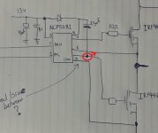
After fixing it 3 or 4 more times, the same fets died and I think it is still a ground loop issue with the Driver chip ( NCP5181 ) Or it could be something else. The fets that keep failing have the longest track length .
I am going to redesign this controller again as V2 is rubbish and I will use have a GND plane and will not have a Current shunt in the Neg rail and put it in the Pos rail before all the Caps and try again. But in the mean time I will fix up V2 again and back off the current to 35 to 40Amps and see how long it will last.
I also have questions about the best way for current limiting as the method I am using is to take the voltage across the current shunt, amplify it and feed it into a comparator so if I set the trigger current to 40amps and when the output of the comparator goes high my Microcontroller code will quickly back off the PWM duty until the current drops below the set point. I will then start to increase the PWM duty again at a slower rate until the PWM value matches the Throttle input. I hope this makes sense.


I was hoping for some advice with my 6fet Sensored BLDC speed controller I have been working on.
This is my 2nd version as my 1st model only got as far as running a motor but decided the whole design was bad so I started again.
After finding a number of mistakes on my V2 board, I finally got it into a bike and sort of running . I am using a 2kw Outrunner motor and the battery pack was made from 120 A123 cells which I wired into a 40V 23A/h pack.
After riding the bike to my friends house which was only 5mins away, when I got home
I decided to increase the current from 40Amps(1500Watts) to 50Amps (2kw)
About 5sec into the ride the fuse went, so the next day I decided my V2 PCB design was also bad but wanted to see if I could make it work by beefing up the ground tracks to the Current shunt. That night the controller worked for about 10mins and then the fuse went again.
After fixing it 3 or 4 more times, the same fets died and I think it is still a ground loop issue with the Driver chip ( NCP5181 ) Or it could be something else. The fets that keep failing have the longest track length .
I am going to redesign this controller again as V2 is rubbish and I will use have a GND plane and will not have a Current shunt in the Neg rail and put it in the Pos rail before all the Caps and try again. But in the mean time I will fix up V2 again and back off the current to 35 to 40Amps and see how long it will last.
I also have questions about the best way for current limiting as the method I am using is to take the voltage across the current shunt, amplify it and feed it into a comparator so if I set the trigger current to 40amps and when the output of the comparator goes high my Microcontroller code will quickly back off the PWM duty until the current drops below the set point. I will then start to increase the PWM duty again at a slower rate until the PWM value matches the Throttle input. I hope this makes sense.
.jpg")