DIY eBike BLDC Motor Controller

Right! I may have those chips tomorrow, they don't have far to travel if they shipped from silicon valley.

I was looking at FET board layout. I came up with a good compact layout for six TO247's. So how much current can we safely handle with six 4110's in TO247 packages?

Another element that has to go with this is a box. Does anyone have suggestions for a nice small box for this? Roughly 2x3x4 inches?? Need to factor the box into the layout.
 
If you're going for TO247 FETs then the two best ones that are readily available are the IRFP4368 (for up to around 65-70V working voltage) or the IRFP4468 (for up to around 90-95V working voltage).

The IRFP4368 has an Rdson of around 3mohm at 100 deg C junction temperature, and has reasonably good thermal conductivity from the junction to the heatsink (probably the most critical parameter). It should be OK for up to around 100A or so reliably.

There are other TO247 packages about, but these two are both easy to buy and have pretty good specs. The downside is the price, but that will come down a lot for a group buy direct from IR.

Jeremy
 
Jeremy Harris said:
If you're going for TO247 FETs then the two best ones that are readily available are the IRFP4368 (for up to around 65-70V working voltage) or the IRFP4468 (for up to around 90-95V working voltage).

The IRFP4368 has an Rdson of around 3mohm at 100 deg C junction temperature, and has reasonably good thermal conductivity from the junction to the heatsink (probably the most critical parameter). It should be OK for up to around 100A or so reliably.

There are other TO247 packages about, but these two are both easy to buy and have pretty good specs. The downside is the price, but that will come down a lot for a group buy direct from IR.

Jeremy

Thanks for the suggestions!
 
Hi, just discovered this thread.

These appeared on my computer yesterday. (And they're just sketches.) Was thinking of starting my own 'cheap high performance controller' thread.

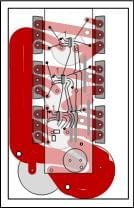
Bottom board is strictly high current and high voltage. Bottom layer shown. Top layer identical except no gate connections. Traces need widened to use available area. Driver fet board connections made where they're convenient for minimum inductance.

The first daughter board is just the drivers (max15013/15019 tentatively?) and 5v power supply (I intend to bring in 12v externally). And the top board (not shown, 18f24431) is little more than the cpu and shunt buffer.

controller top.jpg

An end view, showing the caps below and the driver and cpu boards between the fets.


I want strictly a serial interface (although the board wouldn't be limited to same). The only wires would be to the motor, power in, and the serial cable. I intend to design a handlebar unit, lighting controllers, and possibly a couple others that connect to it. CAN would be neat, but I don't want to be forced to include a CAN controller in my taillight for example, so want a simple serial I/O that I can implement on a 12fxxx PIC for example.

And I, myself, would plan on etching the prototypes myself. Another reason for keeping things simple and uncluttered. The bottom board is drawn 2.5" x 4", and the smaller ones are 1" x 3" and 3.5".

Not trying to hyjack your thread, just thought you might be interested in my proposed fet layout. I've seen people calling for a more efficient layout, but never seen examples of what they mean.

Bob
 
Hi Bob, welcome to the thread. You are looking at some very similar ideas. Great to share whatever fits.

I need to look into DC-DC converters/switching regulators to make the 12V from 24-80V. I found one that works from 17-72V that is off the shelf, three leads, 500 mA. Looks quite practical. Wish it went a bit higher in voltage, but 72V may be just fine. That's 17S. Call it 16S capable. Anyone have experience with these devices? R-78HB12-0.5.

I have some rough sketches of the FET board. Nothing on cad yet. Thinking of 2 layers, mostly +V and -V floods, top +V, bottom -V, and pick up the motor currents with #10 wires to provide adequate current capacity leaving the board.

The ATMega32M1 I have on order has CAN bus as well as serial. 32 pins. lots of I/O and a full motor control subsystem. I'm not planning to use the CAN hardware. It also has LIN hardware.

I am also looking for suggestions on the Capacitor bank. Have not researched that yet. Also have to select a 100A board mount shunt.

I have been looking at drivers. Have not selected those yet. Have to take a look at the ones you mentioned. Looked at so many.

Thanks for any suggestions!
 
Oldswamm,
Instead of the 18F2431, look at the 18F25K22, same 28 pins, but, this has 3 separate PWMs and more 16 bit timers. I believe that this design, separated into different stackable PCBs should allow more than one type of CPU. I use PIC micros all the time and do assembly rather than high level anyway. More compact and efficient. I am more interested in sine commutation and optical phase encoding rather than Hall sensors. Some of this is motor choice dependent. I would not mind contributing if our own CPU choice is possible. I will check the function compatiability between the 18F25K22 and the Atmel part that has been referenced. I use PCAD. Just my 2 cents.
Kenkad
 
Thanks for your input Kencad.

Regardless of the CPU used there are a lot of common elements that can be shared. Just about everything else, aside from part of the PCB layout is the same!

Elements to collaborate on independent of CPU:

FETs, heat flow, impedance, packaging (box)
FET drivers
capacitors
regulators
standard ebike interfaces
functionality
control algorithms and block diagrams
timing, pwm frequency, etc
protection - input, motor shorts, hall to motor shorts, etc

I find the Gnu C Compiler AVR package generates really good code for the AVR CPUs, instead of writing assembler I modify the C code to help it generate the best code, or at least good enough.
 
alan,
That is what Bob showed. Thtt would make this processor independent, just functionality dependent. I do not care where the FET drivers are. Maybe best on the CPU PCB so to keep the FET board clean as possible. I will keep watching. By the way, I looked at the Atmel data sheet, and, it has only 2 indpendent PWMs. I would have thought that for BLDC it would have more than two. Must be just trap commutation or am I mistaken?
Kenkad
 
Alan B said:
Instead of putting the processor between the FETs I am thinking of putting the capacitors between the FETs and putting the processor/etc on a board below the FET PCB. Wonder if caps can be kept short enough to match the TO247 FET height. They are pretty tall anyway.
For what you're thinking, would make for a very compact unit.
I was thinking in terms of allowing people to use as big of caps as they wanted, for the folks who want to SEE if you can push 200A through 6 FETs. That's why it's drawn with big ones. :)

Also, wouldn't the electronics be more likely to tolerate heat than the caps?

With 4 sided boards and SMT for the cpu/drivers, the drivers could be on the bottom and the cpu on the top and the whole thing could be kept on one board under 1" x 3"

The high side drivers are what worry me. If someone could point me to, or send me schematics/specs of known working discrete high side drivers I could study, it would be appreciated.

KenKad, I'd about decided the 2431 wasn't going to cut it, probably chose it because I have some on the shelf. :? They've added a whole swarm of PICs with extra letters in the #s since I last worked with them. :lol: More studying!
 
The ATMega32M1 has a Power Stage Controller module in addition to the usual I/O most AVRs have. This is the BLDC driving system. This is in addition to the two PWM units. It is covered in section 14 of the spec sheet.

I have not used one of these yet, but it claims to have all the necessary stuff to handle sensored and sensorless BLDC control.

You raise a good point about the temperatures, but if we do this right we won't have much heat. CPUs don't like heat either. Anyway, lots of ways to do it.

What's a good baseline design for the caps?
 
Jeremy Harris said:
If you're going for TO247 FETs then the two best ones that are readily available are the IRFP4368 (for up to around 65-70V working voltage) or the IRFP4468 (for up to around 90-95V working voltage).

The IRFP2907 is another one to look at. Rds is spec'd at 4.5 milliohms, but they actually run 3 milliohms. Can be had for 3 bucks a pop. I use them in my welder and rocket launch controllers.
 
texaspyro said:
Jeremy Harris said:
If you're going for TO247 FETs then the two best ones that are readily available are the IRFP4368 (for up to around 65-70V working voltage) or the IRFP4468 (for up to around 90-95V working voltage).

The IRFP2907 is another one to look at. Rds is spec'd at 4.5 milliohms, but they actually run 3 milliohms. Can be had for 3 bucks a pop. I use them in my welder and rocket launch controllers.

Good to know! So many choices.
 
Jeremy Harris said:
If you're going for TO247 FETs then the two best ones that are readily available are the IRFP4368 (for up to around 65-70V working voltage) or the IRFP4468 (for up to around 90-95V working voltage).

The IRFP4368 has an Rdson of around 3mohm at 100 deg C junction temperature, and has reasonably good thermal conductivity from the junction to the heatsink (probably the most critical parameter). It should be OK for up to around 100A or so reliably.

There are other TO247 packages about, but these two are both easy to buy and have pretty good specs. The downside is the price, but that will come down a lot for a group buy direct from IR.

Jeremy
Nice FETS!
I know that a few folks have run their FETs at or near the rated drain-source voltage rating without problems but, IMHO, that's a mistake for a reliable controller design. It just makes the unit too susceptible to the inevitable spikes that will occur.

An industry standard is not to exceed 80% of the rating (and that's assuming VERY good spike suppression) or 50% of the rating for aerospace/military applications where reliability is critical.

I know how unpopular this idea will be but it seems that there are a lot of threads lately about designing reliable devices. Seems to me that one reason this is happening is because the ratings are being pushed too hard and accepted standards for reliability are being ignored in existing designs. These standards come out of millions and millions of device hours of use and really do help to ensure a reliable system. :mrgreen:

But, derating a FET's Vds value does make it harder and/or more expensive to design a controller so I do understand why it's done so often. I'm just glad that these threads are popping up and am really excited to see the devices that come to light!!
 
I strongly recommend placing the drivers on the FET board! Keeping the driver ouputs to within a quarter inch or so of each FET's gate will help a lot in keeping FET the on/off times fast and reducing ringing. And careful layout of the FETs and their PCB traces will definitely help in reducing the inductance of the board, allowing you to use smaller capacitors, less protection circuitry, and lower voltage FETs.

IMHO, a 4-layer board is a necessity here. Yes, it can be done with two layers. But, 4 layers allows for enough copper to (probably) eliminate the need for "bus bars" and also eliminates long discrete wires running to the gates. Single-sided assembly might be possible, depending on the layout, but double-sided isn't any harder to do than single-sided when hand soldering is involved.

[Edit] And, very importantly, while beefing up the FET board traces can help a bit with lowering the inductance (and certainly the resistance) it isn't nearly as effective at reducing inductance as shortening the traces. And while paralleling FET traces (top/bottom of the board) can increase their current handling ability, having the source and drain traces for the FETs aligned on the top/bottom of the board can significantly reduce the trace inductance because of the coupling between the traces. The layout of most existing controllers shows very little attention to this and, IMHO, is another cause for their lack of reliability. Packing on more capacitance seems to be their attempted fix but that won't work well with the inexpensive high-ESR electrolytics they often use. Heck, with those layouts, it won't work very well with low-ESR MLCC's either. :)
 
What kind of capacitances/voltage/ripple current ratings do you think you'll be wanting to support on the FET board? I think it would be worth investigating the benefits of using surface mount versions and/or ceramics, tantalums, etc. Yes, everyone uses big electrolytics in controllers. But, these caps often result in a very less-than-reliable controller and I'd love to see if the alternatives are affordable. Or, since they will be more expensive, better quality/reliability usually is :) , if the benefits are worth the cost.

I'd be happy to do the leg work on this but wanted to know where you guys saw your designs heading in terms of what capacitances/voltages/ripple current ratings you feel the design would need or support?
 
Perhaps this is a great opportunity to start from scratch? After all, the total capacitance and mix of capacitors needed is completely different for each controller design/layout and is very strongly affected by the FET choice, FET driver speed, and PCB layout. We can start with a couple of affordable options (medium cap. MLCCs and higher cap. low-ESR electrolytics?) and select the ones that will have the lowest ESR at the frequencies of interest and will still fit on the PCB while still being affordable.

Or...

Just going for the lowest ESR we can get while still fitting on the PCB, and still being affordable, is always another option though. We have no idea what the results will be until the controller is built, but with some serious thought to FET arrangement (no long lines of FETs if just using one driver!!) and trace positioning at least the caps will be as effective as we were willing and able to make them. And there no ugly math to do. :mrgreen:
 
The driver I'm using is the IR2110. It has the advantage of an isolated high side (up to 500V) and comes in a package (14 pin DIP) that makes it easier to get short runs to the FET gates (bearing in mind the need to fit gate resistors). Layout is also simplified because it has the input pins on one side and the output pins on the other.

If using TO247 FETs then the gate drive pins come pretty close to lining up exactly with the gates of a linear FET array, meaning the track lengths can be kept short and straight.

It can drive a couple of amps or so into the FET gates, so can cope with devices with a total gate charge of a few hundred nC and still maintain respectable switching speeds. Bear in mind that you may need to damp down the switching speeds for EMC reasons. Although it would be nice and efficiency to run the FETs with transitions taking a few tens on nS, in reality you probably need to sacrifice a bit of efficiency and go for switching speeds of a few hundred nS. We know that the Xie Chang controllers have switching speeds of a uS or so, yet they are still noisy little EMI generators.

A discrete driver is easy to design, too. I posted a really simple complimentary pair design on another thread, with asymmetric turn on/turn off, that seems to work fine on the bench, driving a FET with a 1400nC gate charge.

Overall the IR range of gate drivers look to be amongst the easiest to work with, although the On Semiconductor range are probably as good.

Jeremy
 
This thread is transforming into a design discussion of a collection of different controller designs, and I think that is excellent! Getting to the specific tradeoffs will help a lot of folks who read this later and are trying to understand the choices.

For my design, outlined in post #2, I have done some tuning. Based on the small switching modules I am finding a max of 72 volts. My battery choices are 16S by 3.7V and 12S by 4.2V so 60V max. The FETs in the 75V max range are better in many specs (such as the ones Jeremy recommended earlier), and the IRFP4368 has been penciled into my selection. 2mV drop at 195A looks good. We don't want the FETs to heat up. I am just planning to use six of these to keep the unit small.

What is a good value for capacitor ripple? I penciled in 2V max. The caps should be no taller than the FETs for my plan.

I agree that moving the FET drivers to the FET board is potentially a good idea. It will require 5V to be added to the inter board connector.

My plan on regulators is to put the switching 72V to 12V regulator on the FET board (all HV confined to that board), and then put the 5V linear regulator on the control board.

Thanks for all the great comments!
 
I agree with Camlight for a 4 layer PCB for the FET PCB, especially if the FET drivers are on this PCB. An alternative is a FET driver PCB that is a daughter PCB, but, this may add issues even though the daughter to FET PCB interconnects are very short. This goes back to a triple stack with the driver PCB in the middle. This would allow for some driver tuning.
Kenkad
 
I am pretty confident you can do the FET board in two layers. One should work really hard to avoid 4 layer boards, particularly in a product that may not be assembled/reworked by pros.

Gate drive lead length (within reason) need not be a big problem. You tweak the series resistance to damp down the edge problems. My welder uses 18 IRFP2907 FETs in parallel. The gates are not wired on the PCB, they are connected by a "flying" hand wired lead. Even using a really crappy gate driver chip, I needed to use a larger than expected gate drive resistor to keep the switching currents below 2 billion amps/sec. I got sub-microsecond gate drive signals without a series resistor. I don't think achieving a very good gate drive rate on a single FET gate will be a problem.
 
Back
Top