DIY eBike BLDC Motor Controller

It even has a Dallas Semi button port for data transfer and permissions (key). :D
Your key could allow different performance with the same machine as mine.
Also, just touching the 'key' to the port at shutdown would transfer the log to your key, and touching it to the button pad by your PC would finish the transfer.
I like it. A really cool find, Alan!
 
oldswamm said:
Didn't look at the details yet, but that 'development Terminal' looks like just about what I had in mind, and an excellent price. Would want the communication interface to be able to accommodate multiple controllers, as well as other boards as yet undefined, such as lighting controllers, etc.

Have you read Shane Colton's thesis? I have only paged through it, but it's very clear and understandable. Very little at all involved math. Guess that isn't as important to you as to me though. :)

I think I'm going to pencil in the HCPL-J312 for high and low drivers.
http://search.digikey.com/scripts/DkSearch/dksus.dll?Detail&name=516-1123-5-ND
Similar to the HCPL-3120 he used, except only good for 900v.

I have not read it yet. Plan to.

I am thinking about using optically isolated multidrop serial for that. Want to be able to talk to controller and BMS's on the same bus. Multiple motor controllers should be no problem.
 
oldswamm said:
It even has a Dallas Semi button port for data transfer and permissions (key). :D
Your key could allow different performance with the same machine as mine.
Also, just touching the 'key' to the port at shutdown would transfer the log to your key, and touching it to the button pad by your PC would finish the transfer.
I like it. A really cool find, Alan!

Great ideas!

Sparkfun also has RFID and cellular modems as well as tiny GPS's. Could do some very interesting things.
 
I'll get back to the Capacitor bank design later. Still looking for examples, suggestions and design information.

Note that some of the FET drivers have shoot through protection and some don't. Have to review the selections carefully.

Have updated the second posting with new information on requirements and design.

Here is the 12V regulator I've been looking at. Three terminal regulator module handles up to 72V input. Replaces a standard three terminal regulator but contains a switching module. Compact footprint.

Innoline R-78HB

http://search.digikey.com/scripts/DkSearch/dksus.dll?Detail&name=945-1057-ND
 
Alan B said:
Not part of the controller, but a good choice for a contactor for your system. This suggestion comes from member boostjuice:

Tyco EV200

http://relays.tycoelectronics.com/datasheets/ev200.pdf

Why do you want a contactor on a BLDC system?

I can fully understand this being essential on a brush motor system, as a common failure mode drives the motor at full speed (shorted FETs). The same can't happen with a BLDC system though, so all that's needed is a big fuse (solely to prevent fire damage from a shorted battery - the fuse will only blow if there's been a catastrophic failure).

It isn't common practice to fit contactors on ebike BLDC systems, although there's no real reason why you couldn't fit one if you really felt it was worth the space it takes up. The easiest (and probably cheapest) way to isolate the battery quickly is a simple shorting link. Something like a Deans connector is tiny and will take about 70A, so makes a pretty good 'switch'. If you want to deal with the high inrush current problem at power on, then wire a switch to turn on the controller electronics and apply power to a capacitor pre-charge resistor, then you can insert the shorting link with no sparks. If you really want to go for more safety, then fit the Deans shorting link on a lanyard clipped to your person somewhere, so if you fall off the link is pulled out.

Jeremy
 
Just for those who are interested in a master switch. This contactor is probably better for an e-motorcycle than an e-bike, due to the space it takes. It is more power efficient than I expected for its size. It might be nice to run this from the "kill" switch on the handlebars. If the motor or controller start smoking it would be nice to have a quick thumb operated shutoff.

I do like your shorting plug approach.
 
Well, that 'display/controller' doesn't really have a Dallas Button port, just a one wire LAN port, which is what I suggested in an earlier post for the controller, for temperature monitoring. After the idea occurs to me though, I like the idea of including one in the handlebar unit. Here's a pic for those of you who don't know what I'm talking about. A button in a keychain adapter, a two button unit for the home PC, and the through hole unit we would probably use here, includes an LED so it's easy to find in the dark, and so the programer can signal the user that transfer was successful.
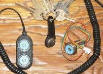
Dallas buttons.jpg
<edit> And since each button, whether its flash memory, or a real time clock, has it's own unique serial #, any one button can be given it's own set of 'permisions'. You could have a button that only allowed the bike to go 1000m from it's starting position at a set power limit, so you could let people ride without worrying about the bike coming back, or they're killing themselves!

Yea, Alan, the serial to the BMS(s) should have been at the top of the list! Do you have your BMS designed yet? Mine would use a pic, out of habit, but? :)
I also intend a very simple board that can control lights (tail, turn, stop, head, hi head (halon?), strobe), but could also be used for delta/wye, serial/parallel (batt or motor), or for main power contactors (none of which I intend to use, but for anyone who did, it's there)

Jeremy, the reason I might consider a power contactor would be to make battery connection idiot proof. The processor would make sure the caps were charged through the same resistor its getting power through before it closed the mains.
If we have 5000uF+ @ <10mOhm, and 20Ah 30C LiPo, and plug the batteries in, we get a LOT of current for a very short while! I don't think I could/would do that. If I'm that wasted, I don't fool with guns, dynamite, or, when/if I can afford them, LiPo. :D

My intention when I have real batteries to worry about is to use a precharge connector (and to leave the dangerous things on the shelf or parked on those rare occasions when under the influence).

I do like the idea of a quick disconnect, especially during prototyping.

To Alan, I saw Sparkfun had GPSs, but where are the compasses, (with tilt and trim)? :) Available elsewhere, but I wonder that they don't have them. I would like to have that in addition to the GPS. Either could be implemented with a(the) simple serial interface.
The drivers I suggested do have shoot through for themselves, but if we use individual drivers for each fet, we almost have to design our own shoot through protection, I would think. In order to have built in shoot through protection, you almost have to have a driver with both high and low outputs such as the MAX15018, don't you?
 
I believe Sparkfun has magnetic field sensors, even multi-axis. They may not call them compasses. Operating a magnetic compass near this much current is going to be problematic. Probably need to remote that sensor a bit to get away from the wiring.

I put in an order to Sparkfun this morning and it already shipped!

To have in-chip shoot through protection it pretty much has to be a high/low side integrated chip. I would hope that at least one of the many products on the market would be suitable to use.

It would also be nice to have a direct disable to the drivers. Then we could run the ebrake / emergency switch direct to the drivers to really shut things down directly.

Looks like we need phase current sensors if we want to be able to do sine control. Only two are required. But if we want to detect shorts quickly we may also need a battery shunt. So might need 3 shunts total.

Lots of choices.
 
They have a GPS module with a built in compass and 3-axis accelerometer: http://www.sparkfun.com/commerce/product_info.php?products_id=9838

The biggest problem with compass modules is the ones with 3-axis tilt compensation are rather pricey... but then I once bought some Precision Navigation 3-axis magnetometer/compass modules for around $600 each and they were dirt cheap bargains at the time.
 
Alan B said:
I believe Sparkfun has magnetic field sensors, even multi-axis. They may not call them compasses. Operating a magnetic compass near this much current is going to be problematic. Probably need to remote that sensor a bit to get away from the wiring.
One track mind. Can't think and search at the same time. :) Figured I'd mount it on the strobe light mast. $60 is a bit, but like TXpyro said, compared to yesteryear....

Alan B said:
Looks like we need phase current sensors if we want to be able to do sine control. Only two are required. But if we want to detect shorts quickly we may also need a battery shunt. So might need 3 shunts total.

I've planned on a main shunt plus one on each of 2 phases from the start. One of the things I wish I could get some input on. Seams to me that the 'main' shunt would give us our summed current with less calculation, wouldn't it?

Bob
 
oldswamm said:
...

I've planned on a main shunt plus one on each of 2 phases from the start. One of the things I wish I could get some input on. Seams to me that the 'main' shunt would give us our summed current with less calculation, wouldn't it?

Bob

Reducing calculation is probably not an issue with the processors we are using. The reason I'm considering a main shunt is to react to shorts in hardware quickly.
 
Alan B said:
Reducing calculation is probably not an issue with the processors we are using. The reason I'm considering a main shunt is to react to shorts in hardware quickly.

The main advantages with the hardware driven controllers seems to be that there is no code running to generate the commutation sequence (so if there is a glitch mid-step nothing awry happens - they even change direction instantly, at any point in the sequence) and they have cycle-by-cycle PWM current limiting, so respond to shorts etc in much less than one PWM pulse length, with no code running that might glitch.

Cycle-by-cycle limiting comes close to phase current monitoring in terms of maintaining closed loop control and avoiding current overshoot (a known problem with both the Infineon and Chinese ucontroller driven controllers) Assuming you want to run at around 20kHz or so PWM frequency and want current control down to about 10% duty cycle, then you need to read ADC values, do the calcs and cut the PWM pulse width in less than about 5uS. The hardware approach does this easily down to less than 5% duty cycle at PWM frequencies up to maybe 50kHz or so, but can a ucontroller system respond like this? Maybe, with the right controller and some good code, but my gut feeling is that it will be challenging.

Jeremy
 
Alan B said:
Reducing calculation is probably not an issue with the processors we are using. The reason I'm considering a main shunt is to react to shorts in hardware quickly.
I don't see why a main (battery side) shunt would be any faster than a phase current shunt. In fact for fast reaction time you would usually prefer a phase side shunt, since battery side shunts are most often slightly isolated from fast current changes by the FET capacitor bank.


Jeremy Harris said:
Cycle-by-cycle limiting comes close to phase current monitoring in terms of maintaining closed loop control and avoiding current overshoot (a known problem with both the Infineon and Chinese ucontroller driven controllers) Assuming you want to run at around 20kHz or so PWM frequency and want current control down to about 10% duty cycle, then you need to read ADC values, do the calcs and cut the PWM pulse width in less than about 5uS. The hardware approach does this easily down to less than 5% duty cycle at PWM frequencies up to maybe 50kHz or so, but can a ucontroller system respond like this? Maybe, with the right controller and some good code, but my gut feeling is that it will be challenging.
I understand your view of the importance of fast cycle by cycle reaction time for sensing overcurrent events, but do remember that the current change rate (as limited by the motor inductance/resistance) is not at all as fast as the PWM cycle. Also, many other factors might slow down the real current sense reaction time even when a hardware-based IC is used, such as the battery shunt capacitor bank isolation issue mentioned above, along with a shunt resistor noise filtering/amplification delay and possibly some reaction time for the comparator circuit in your IC.

I think of current limiting actually in two different ways: The primary function is required for the current limiting loop, so this sampling/reaction time is only needed to be as fast as the loop itself (which isn't ususally very fast). The secondary function (OC shutoff) is only needed when there is a problem with the current control loop reacting fast enough, which would normally only happen in a unusual situation such as a motor phase short or something else extreme. As we have found out in other threads, recent ebike controllers have these two distinct current limiting mechanisms built in already. However there are some improvements to be made to these designs so that the primary (soft) current limit would work better.


Jeremy Harris said:
The main advantages with the hardware driven controllers seems to be that there is no code running to generate the commutation sequence (so if there is a glitch mid-step nothing awry happens - they even change direction instantly, at any point in the sequence) and they have cycle-by-cycle PWM current limiting, so respond to shorts etc in much less than one PWM pulse length, with no code running that might glitch.
I know you're not a big fan of motor control MCUs, just as I am not a fan of motor control IC's anymore. While I partly do understand why you don't like the idea of a small firmware program being in control of your motor, I must say that the basic motor commutation code required is *very* simple if you are using an MCU with a dedicated motor control peripheral. It's just a state machine with just a few possible values.

Pat
 
ZapPat said:
I understand your view of the importance of fast cycle by cycle reaction time for sensing overcurrent events, but do remember that the current change rate (as limited by the motor inductance/resistance) is not at all as fast as the PWM cycle. Also, many other factors might slow down the real current sense reaction time even when a hardware-based IC is used, such as the battery shunt capacitor bank isolation issue mentioned above, along with a shunt resistor noise filtering/amplification delay and possibly some reaction time for the comparator circuit in your IC.

I think of current limiting actually in two different ways: The primary function is required for the current limiting loop, so this sampling/reaction time is only needed to be as fast as the loop itself (which isn't ususally very fast). The secondary function (OC shutoff) is only needed when there is a problem with the current control loop reacting fast enough, which would normally only happen in a unusual situation such as a motor phase short or something else extreme. As we have found out in other threads, recent ebike controllers have these two distinct current limiting mechanisms built in already. However there are some improvements to be made to these designs so that the primary (soft) current limit would work better.

I was thinking of the cases where the motor inductance doesn't limit the rate of rise effectively, like a phase short or a low inductance, low resistance motor (which I'll admit is where I'm focussed at the moment). Having the ability to limit within a PWM cycle does provide a neat way of limiting peak output current and possibly providing a degree of protection to the controller under extreme conditions.


ZapPat said:
I know you're not a big fan of motor control MCUs, just as I am not a fan of motor control IC's anymore. While I partly do understand why you don't like the idea of a small firmware program being in control of your motor, I must say that the basic motor commutation code required is *very* simple if you are using an MCU with a dedicated motor control peripheral. It's just a state machine with just a few possible values.

Pat

It's not that I'm not a fan of motor control MCUs at all, I'm just wary of using a general purpose MCU for motor control. The dedicated motor control MCUs deal with the fast and thorny bits of the design in hardware, leaving the code to do the supervisory stuff. This just seems a more sensible approach to me. I've been seeing lots of talk about different MCUs, which seems to focus on the extraneous stuff, like programming tols etc, when I think the selection really should be driven towards MCUs with dedicated motor control hardware on board. If nothing else, I am sure this will result in greater reliability and make the job of designing the housekeeping code a lot simpler, leaving more time to add fancy features.

Jeremy
 
Jeremy Harris said:
I was thinking of the cases where the motor inductance doesn't limit the rate of rise effectively, like a phase short or a low inductance, low resistance motor (which I'll admit is where I'm focussed at the moment). Having the ability to limit within a PWM cycle does provide a neat way of limiting peak output current and possibly providing a degree of protection to the controller under extreme conditions.

True indeed, and I dig what you are talking about when you say that we need higher PWM frequencies along with cycle by cycle current limiting for such low inductance motors. What I was responding to was your opinion that we need to sample the current at a speed much faster than the PWM period (10% of the PWM period in your example) to have good cycle by cycle current limiting for low inductance motors. While the ADC's sample time will limit what maximum PWM frequency you can use cycle by cyle current limiting with, it shouldn't be a problem even if it takes a fairly large part of the period to sample and convert. This sample is fed into a comparatively slow current control loop anyways (either firmware-based or hardware, both will have a certain lag and reaction speed).

But of course this doesn't mean that I wouldn't *love* to have an ADC that could sample and convert with good precision in 1/10th of a PWM cycle - it's just that it's not necessary to be that fast for the main current limiting loop.

BTW, what LR time constant are we looking at for that big colossus motor anyways? Medium sized hubs are about 1ms which is fairly slow compared to the PWM frequency (even if at 16kHz). I'm not sure what X5's or bigger hubs are, but it's probably only slightly less than that. For those big RC motors though, 50kHz PWM with true cycle-by-cycle phase-based current control would probably be the ticket! Higher PWM frequencies would also be great for high RPMs, or else the motor commutation pediod tends to get uncomfortably close to the PWM period which just doesn't seem right.

Pat
 
The hardware in the Micro chosen for this build (ATMega32M1) appears to be well suited to this motor control application. Here are a few words from the press release:

"...
Based on the high performance AVR 8-bit RISC architecture, the ATmega16M1 and ATmega32M1, integrate all of the basic peripherals necessary to satisfy the needs of complex algorithms. Integrating analog blocks like 10-bit ADC, with differential amplifiers and programmable gain options, Analog comparators with selectable comparison levels, interrupt on pin change I/Os. The microcontrollers provide all necessary resources to control BLDC motors in their system environments.

The ATmega16M1 and ATmega32M1 include independent positive and negative comparator inputs to allow sensorless motor control with no external active components. Three individual comparators are available for back Electro Magnetic Field (EMF) measurements. An additional comparator is available for over-current detection. Its reference (comparison level) can be fixed via the DAC output or any external reference voltage. Clocked up to 64-MHz, the 12-bit versatile synchronous Power Stage Controller generates 6 complementary programmable high speed and precision signals to control a motor’s 3 half bridges. The maximum frequency is 64 kHz, with a resulting voltage resolution of about 1/1000. Hardware fault detection will automatically and immediately put the motor in a safe position in case a failure is detected.

About 2 Kbytes of Flash (20 bytes of SRAM) is necessary for the low level drivers for the PSC [Power Stage Controller]. Typical code size for BLDC sensor drive is about 2.7 Kbytes of Flash (about 350 bytes of SRAM). BLDC sensorless drive is about 3 Kbyte of Flash and 300 bytes of SRAM. ... For applications that may require more code, a 64 Kbytes version will be introduced later in 2008.

ATmega16M1 and ATmega32M1 offer a unique feature combination to safely and securely run any brushless DC motor via the appropriate driver and power elements. Effective Power stage controller and integrated analog functions generate a limited number of interrupts, reducing the code size and improving the real-time behavior of the applications.
..."

I will review their reference design before I make the schematics of my design. The above mentions one current trip comparator/DAC available in the chip for current trip, so I suspect that a battery shunt is required for that. There are three comparators needed for sensorless drive. So there are probably not enough comparators for individual phase current trips. There appear to be four comparators on the chip. One could add external comparators but it does not appear to be needed.

The two phase current shunts required for sine control would feed differential amplifiers and ADCs but not comparators. So phase overcurrent can be reacted to on processor time scale, but battery overcurrent can be reacted to on hardware time scale.

I expect Motor winding shorts require hardware time scale reaction to prevent damage.
 
Would it be fairly easy to make this controller amperage based instead of PWM based throttle control? Example, amp limit is set to 30a. At 1/3 throttle the controller will deliver up to 10a instead of just 1/3 duty cycle with 30a max.
 
johnrobholmes said:
Would it be fairly easy to make this controller amperage based instead of PWM based throttle control? Example, amp limit is set to 30a. At 1/3 throttle the controller will deliver up to 10a instead of just 1/3 duty cycle with 30a max.
Yes - At least easy once the current control loop is done. Also for torque control the current control loop needs to be based on motor (phase) current, not battery current. Once this is done, you just use a variable current limit in the PID or hardware loop that's based on the throttle position instead of being a fixed limit.

I think the ideal control will be a bit more complex than this basic torque mode though, like adding back a bit of throttle-based RPM limiting to avoid some unwanted throttle behavior.

Pat
 
ZapPat said:
BTW, what LR time constant are we looking at for that big colossus motor anyways? Medium sized hubs are about 1ms which is fairly slow compared to the PWM frequency (even if at 16kHz). I'm not sure what X5's or bigger hubs are, but it's probably only slightly less than that. For those big RC motors though, 50kHz PWM with true cycle-by-cycle phase-based current control would probably be the ticket! Higher PWM frequencies would also be great for high RPMs, or else the motor commutation pediod tends to get uncomfortably close to the PWM period which just doesn't seem right.

Pat

The small (Turnigy 80-100 size) Colossus is 40mohms and 26uH, so an LR of around 1uS. I don't have the figures for the 12kW version, but guess it will be lower...................

These things are a bit of a challenge to any controller, really, which is why I've opted for hardware cycle-by-cycle limiting and closed loop control I may try and implement current-mode throttle control at some point, as I'm sure it'll feel better.


johnrobholmes said:
Would it be fairly easy to make this controller amperage based instead of PWM based throttle control? Example, amp limit is set to 30a. At 1/3 throttle the controller will deliver up to 10a instead of just 1/3 duty cycle with 30a max.

The only way the controller has to limit current is to cut the PWM duty cycle, so whatever means you use to initiate any limit (speed, current etc) all you can actually alter is the PWM duty cycle (or turn the controller off).

Jeremy
 
Jeremy Harris said:
The small (Turnigy 80-100 size) Colossus is 40mohms and 26uH, so an LR of around 1uS. I don't have the figures for the 12kW version, but guess it will be lower...................
These things are a bit of a challenge to any controller, really, which is why I've opted for hardware cycle-by-cycle limiting and closed loop control I may try and implement current-mode throttle control at some point, as I'm sure it'll feel better.
hummm... I calculate the L/R of a motor with 0.000026H and 0.04Ohms as being about 650us? 1us would seem like an insanely short electrical time constant for any motor it seems to me. I checked Justin's simulator and collected his L and R data for a few different motors and found these L/R results for DD hubs: 9C - ~2.2ms ; Xlite5302 - 1.7ms.

So if the L/R ratio really is about 1/3rd, passing from 16kHz PWM to about 44kHz or so should compensate for the difference in the motor's electrical time constant difference, and we would then have similar current ripple to deal with.

Pat
 
johnrobholmes said:
Would it be fairly easy to make this controller amperage based instead of PWM based throttle control? Example, amp limit is set to 30a. At 1/3 throttle the controller will deliver up to 10a instead of just 1/3 duty cycle with 30a max.

Yes. Once we have a working motor control algorithm we can drive it with whatever we can think of in terms of algorithms.

One algorithm I was thinking of that might be interesting is "combined limit control". Map the throttle at 0-100% as a limit onto several parameters at the same time, whichever one hits the limit first drives it. So it could simultaneously limit on speed, battery current and phase current. Set dynamic limits on all three based on throttle position, and whichever one hits its limit controls the PWM. A feedback loop driving PWM does the actual control.
 
Alan B said:
Yes. Once we have a working motor control algorithm we can drive it with whatever we can think of in terms of algorithms.

One algorithm I was thinking of that might be interesting is "combined limit control". Map the throttle at 0-100% as a limit onto several parameters at the same time, whichever one hits the limit first drives it. So it could simultaneously limit on speed, battery current and phase current. Set dynamic limits on all three based on throttle position, and whichever one hits its limit controls the PWM. A feedback loop driving PWM does the actual control.


That sounds like just what I want. Kinda trying to mimic 4 stroke ICE throttle response.
 
Alan B said:
Once we have a working motor control algorithm...

Gee, you've had the micros for a couple days now... Where's the beast? :roll: Gary would have been though a half dozen iterations of the circuit board by now :lol:
 
Back
Top