DIY Toroidal Axial Flux PM

stan.distortion said:
Tooth sizes and profiles may help, the biggest teeth possible would probably make sense to reduce the effect of the inherit tolerance limitations of printing and helical might not be helping, even that very slight overhang can effect finished dimensions badly. Not sure if you're using a raft, the steep temperature curve immediately above the bed really screws around with dimensions for me but that's probably just my settings, materials etc. Often thought alternative tooth profiles and methods could be better for 3dp, similar to a sprocket with the mating gear using small bearings as rollers for example. Looking really good
Thanks,
yeah I have found some goldilocks zone with my printer where I am getting virtually zero elephants foot, and getting great bed adhesion, and was actually able to print the all the gears without a brim or raft.
 
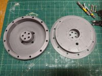
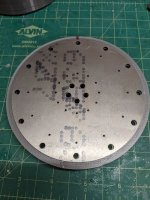
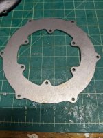
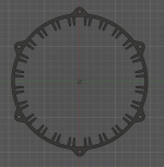
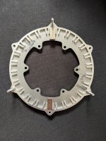
I have the new version of the stator mold printed, and I got a laser cut piece for the top of the mold to keep the screws from destroying the plastic. Hoping to get a number of uses out of this one.
PXL_20220316_202931155.jpg
PXL_20220316_203004535.jpg

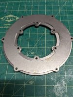
I also ordered some new rotor back irons while I was at it. I reduced the size even further brining in the OD 2mm and the ID out several millimeters. I also shrank the mounting holes to match the OD. They are now down to M2.5. These might be too small. but I'm hoping there's power in numbers.
PXL_20220316_202837161.MP.jpg
new on top of the old
PXL_20220316_202819092.jpg

I tried to get the magnet jig pieces made out of carbon fiber, but unfortunately they were not able to get the tolerances I was hoping for. So I had some made out of aluminum, they should be here soon. I'm really hoping I'm not missing something and end up causing a magnetic short. If someone is more familiar with this area, I would love to know more.

I made some progress with the cores, but not much. I printed a few test cores and a jig that I am hoping to use, but I keep tossing around a few ideas, and haven't really pursued anything yet.

but the most exciting news. I think I will have a metal rotor hub soon! This should sort some of the issues with things not being true. Which should allow me to balance things. Lots of moving parts right now.
 
HalbachHero said:
I tried to get the magnet jig pieces made out of carbon fiber, but unfortunately they were not able to get the tolerances I was hoping for. So I had some made out of aluminum, they should be here soon. I'm really hoping I'm not missing something and end up causing a magnetic short. If someone is more familiar with this area, I would love to know more.

Looks great so far. I don't understand the question about magnetic shorting. I might need a picture to understand.
 
With the Emotor program u can plug in the dimensions and simulate the magnetic circuit. I don’t think there’s any simple statements that can be said related to that and depends on specific design. It’s a pretty simple program as long as u can make the needed files representing the rotor.
 
fechter said:
I don't understand the question about magnetic shorting. I might need a picture to understand.

the part that surrounds the magnets. I have been making it in plastic, but I have some aluminum ones coming in the mail. I realize aluminum is non-ferrous, but it does produce eddy currents when subjected to a changing magnet field. Maybe a magnetic short is not my concern, but would be more from having back emf from the stator causing eddy currents in the aluminum.

Screenshot 2022-03-17 172649.png


Hummina Shadeeba said:
With the Emotor program u can plug in the dimensions and simulate the magnetic circuit. I don’t think there’s any simple statements that can be said related to that and depends on specific design. It’s a pretty simple program as long as u can make the needed files representing the rotor.
Yeah I may try to make this in FEMM and see if I can glean anything from that. Could you provide a link to the Emotor program. I am not seeing that with some simple googling. Thanks!
 
HalbachHero said:
the part that surrounds the magnets. I have been making it in plastic, but I have some aluminum ones coming in the mail. I realize aluminum is non-ferrous, but it does produce eddy currents when subjected to a changing magnet field. Maybe a magnetic short is not my concern, but would be more from having back emf from the stator causing eddy currents in the aluminum.

OK, I see now. There will be some minor eddy currents in the aluminum, but I don't think it will be significant. The flux path will sort of jump over the aluminum as it goes from one pole to the next. The flux won't change much in that area.
 
fechter said:
OK, I see now. There will be some minor eddy currents in the aluminum, but I don't think it will be significant. The flux path will sort of jump over the aluminum as it goes from one pole to the next. The flux won't change much in that area
Cool, I'm hoping that the case. I got 2.0mm thick aluminum, and the magnets stick 3.5 mm off the face of the back iron, so they are sunk in a bit from the face of the magnets, this may help further.

I should be able to get the new rotors mostly made this weekend, and maybe some progress with a new stator. We shall see.

PXL_20220319_150312189.jpg
 
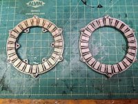
A new personal record. I made these rotors in about 35 minutes. The aluminum is not quite as tight of a fit on all the magnets as the plastic was, so I worry some of the halbach magnets are maybe slightly tilted, but it came together nicely. Just need to let them cure now, my least favorite part.

PXL_20220319_202437104.jpg
 
What keeps the magnets in place while the glue is curing? They would have a tendency to jump out of the slot and flip over.
 
fechter said:
What keeps the magnets in place while the glue is curing? They would have a tendency to jump out of the slot and flip over.
Before I used to try to press them in place with a wood block. But with this and the last one, It seems that they stick well enough to the back iron that I dont need to hold them in place. I found that a few slid around a little bit, so I may use something to still hold them in place in the future, but it seemed to work well just sticking them on and correcting those that looked a bit off by hand.

I recorded this one, so I plan to put together a build video as I complete another stator.
 
back from more radio silence. I had gone on vacation, so I've been quiet lately, but my mind has been all over the place lately with what I want to do next.

So I decided pretty much immediately that I don't like these rotors. because I think the amount of aluminum you can fit (at most the thickness of the magnets) is not going to be strong enough. So this has led me to change the design of the rotor once again. even though I just made new ones.... I'll try to make them useful. I think the new design will work out better, even though there is more steel, the hub piece that ultimately needs to be machined, is smaller, therefore hopefully cheaper to make.
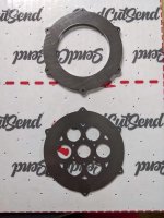
PXL_20220407_174001462.jpg

I also had someone reach out to me since my last youtube video and offered to machine a part for me. I sent him the version that I had working at the time. Unfortunately there were some things about the model that I had done for plastic, and long story short there are some issues with tolerances that might be an issue, but its super cool to see it losing plastic and gaining metal.
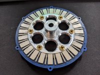
PXL_20220409_172441489.jpg

I thought about making ferrous cores, either simply printing with a partially iron filament (I realize this is not great), or making them with a mold in some ways previously mentioned. I have made a few plastic prototypes that I think I like, but they might be fragile because of the small features on them.
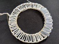
PXL_20220409_172528781.jpg

I also was thinking a lot about a suggestion I have heard multiple times. Why not just wind it around the cores initially. I am thinking of making a jig that magnetically holds everything in place using one of my previous rotors as the magnet. I'm hoping it will be strong enough to hold the ferrous cores in place while I wind around them.
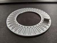
PXL_20220409_172500390.jpg

Also I was going to just wind a stator, but ran out of wire pretty fast, and realized I needed to refill the litz wire machine and decided that my garden was more interesting.... But I have been spending some time on another goofy tool that I'm hoping will make winding these things even easier, but we will see....
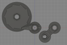
Screenshot 2022-04-13 080811.png
PXL_20220413_120514092.jpg

The idea is that the cam will be connected to the swinging arm and another point on the frame with elastics. when I pull the swinging arm out, it will lock the spool from unrolling. I should be able to pull the wire out, and then the swing arm should pull the wire back a bit and release the lock. This way instead of doing one lap with one phase at a time, then playing catch up with the other phases. This meant I had to keep moving those weird pen spool things I had around the jig. I would drop them from time to time, or the wire would snag something, and it resulted in the it all unspooling. This way the wires will always be in one place. I think I will need to refine it a bit, but so far its come together nicely
 
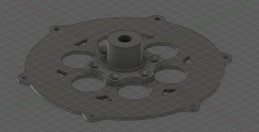
Here's another image of the new back iron with the new hub that I am thinking. This reduces the amount of material that needs to be machined, and allows the laser cut steel to act as the main structural piece inside magnet ring. I might tweak the aluminum part some more so its even easier to make, and ultimately I will probably need larger screws. They are only M2.5, I'm not sure how much force those can take before they shear.
Screenshot 2022-04-13 082417.png

Also, a question for the community. Would it make more sense to use stainless steel screws or brass screws, or some other material for the screws that are very close to the magnets. Obviously I managed to move the inner diameter ones away, but there are still some in the stator, as well as the ring around the outside. I'm not even sure what material property to be looking at to know what's a better choice, but I would assume the shear strength of steel is greater than brass.... Thoughts?
 
Also, happy cake day to this thread. I just realized I started posting a year ago today. Its been quite a journey, I'm excited to see where it goes in the next year(s)
 
My understanding was that your aluminum piece was to hold the magnets in place while glueing and making up some width. I don't see it as an issue. The glue should hold the magnets in place. Also, having a spot to machine in the aluminum could be helpful for balancing.
Anything 2D will be cheaper to make vs 3D. Anything off the shelf will be cheaper at starting quantities than making things from scratch.
I think the M2.5 screws could work but tightening tiny fasteners correctly is tough. I think you will find the tiny brass screws are nowhere near strong enough, maybe the stainless as well.

It's also hard to understand the complete design from some pictures of the parts. Seeing some pieces but not exactly sure how it all goes together.

In place of the ratchet / pawl consider one way bearings for some cost to effort help.
For winding you could look at printing a core holder that has a spot to drop all the cores in that has a few little plastic tab hooks to hold them all in place. Magnets could work too.
 
Jrbe said:
My understanding was that your aluminum piece was to hold the magnets in place while glueing and making up some width. I don't see it as an issue. The glue should hold the magnets in place. Also, having a spot to machine in the aluminum could be helpful for balancing.
Anything 2D will be cheaper to make vs 3D. Anything off the shelf will be cheaper at starting quantities than making things from scratch.
I think the M2.5 screws could work but tightening tiny fasteners correctly is tough. I think you will find the tiny brass screws are nowhere near strong enough, maybe the stainless as well.

It's also hard to understand the complete design from some pictures of the parts. Seeing some pieces but not exactly sure how it all goes together.

In place of the ratchet / pawl consider one way bearings for some cost to effort help.
For winding you could look at printing a core holder that has a spot to drop all the cores in that has a few little plastic tab hooks to hold them all in place. Magnets could work too.

The aluminum was really just to fill the void in the center, but needed to be structural for any axial loads. I made the steel a minimal as possible because I had initially dreamed on it not having a center and becoming a donut. But I realized I care more about spinning it faster which means smaller diameter bearings and such. So I flip flopped a bit.

I held the magnets in place with some 3D printed pieces, but removed them before the epoxy cured. I should have just left them in and popped them out afterwards.

If I shear some M2.5 screws. I can always bump it up I suppose... but that might mean catastrophic failure when that happens. We shall see!

I dont want to use one way bearings because it does need to be able to spin both ways, but not all the time.

yeah I thought of tabs in some way, but they are really small and I think if the cores were ferrous enough it will have enough pull that magnets should work. And it would give some old junk rotors a new purpose hopefully.

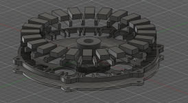
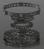
I took some screenshots of my attempt at an explosion of one rotor and the stator hub. You'll have to imagine the screws, the other rotor, and the stator itself. The stator would sit around that spiky ring thing. Hope that's helpful.
Screenshot 2022-04-13 121602.png
Screenshot 2022-04-13 121907.png
Screenshot 2022-04-13 122101.png
 
Nice to see such progress HH, really like the exploded view, it's hard to tell what your doing sometimes until it's done.
(I'd go with stainless screws over brass, Ti might be best magnetically.)

It will be interesting to see what the ferrous core parts do in the coming days,.. won't know till you try of course, and I for one will sure like to see, but as the steel content goes up, so does the axial stresses on the stator and rotors, as we all know. Hopefully there's a goldilocks mixture to be found. :wink:

Happy motor cake day!
Happy Cake Day.jpg
 
I'm not sure how a pulley is attached / power transfer happens.
2 bearings or 4?
Shaft is attached to stator?
Not sure what torque you're aiming for but the stator needs to be able to take the output torque force as a force 90° to the side of the stator. Your stator deflection at that force needs to be less than the magnet / stator gap so it doesn't rub. Stator might also chatter if it's floating / can wiggle. That's the only thing I currently see as a potential issue area from what I understand of your design.
 
APL said:
Nice to see such progress HH, really like the exploded view, it's hard to tell what your doing sometimes until it's done.
(I'd go with stainless screws over brass, Ti might be best magnetically.)

Have I mentioned how much I regret choosing this username....
Thanks! This is the first project I have ever really tried to 3D model, and I have learned a lot over time. I feel like I can really use it as a tool now and it's certainly useful to show how everything is assembled. Ti is a good idea. I imagine they cant be too expensive for some small ones.

APL said:
It will be interesting to see what the ferrous core parts do in the coming days,.. won't know till you try of course, and I for one will sure like to see, but as the steel content goes up, so does the axial stresses on the stator and rotors, as we all know. Hopefully there's a goldilocks mixture to be found.
Yes this is a whole realm of stuff I know very little about, so there will bee a lot more learning ahead. I am curious if the epoxy stators have any chance of working once there is iron in them, but I guess we will have to find out. I am hoping for some balance in the forces acting on the stator to not constantly stress it, but its probably going to be more along the lines of something completely opposite. It might be constantly being pulled from one side to the other, which obviously will wear things out over time.

APL said:
Happy motor cake day!
Ha! I love it thanks


Jrbe said:
I'm not sure how a pulley is attached / power transfer happens.
2 bearings or 4?
Shaft is attached to stator?
Not sure what torque you're aiming for but the stator needs to be able to take the output torque force as a force 90° to the side of the stator. Your stator deflection at that force needs to be less than the magnet / stator gap so it doesn't rub. Stator might also chatter if it's floating / can wiggle. That's the only thing I currently see as a potential issue area from what I understand of your design.
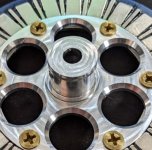
There are 2 bearings with a spacer between them. But one part that is missing from the design is a recess in the rotor hub that allows an e-clip to be attached. This is what hold the stator in place on rotor hub. I have experienced wiggling, but I have assumed its been due to compliance with the plastic parts. The bearings seem to fit quite snug, but it could be another factor that I am missing.
Power transfer is through a shaft that is inserted into the center hole on the rotor hub. In the past the was D shaped so that I could print it to size and smack the shaft in place. The Aluminum version (and I will try this with a printed one), has a set screw to hold the shaft in place.
PXL_20220409_172441489 (1).jpg
PXL_20220408_222603886.jpg
Hope those help
 
HalbachHero said:
Screenshot 2022-04-13 121602.png
Screenshot 2022-04-13 121907.png
Screenshot 2022-04-13 122101.png

Yeah, Blender! What's your workflow if I may ask ? All in blender than direct print, or export to cad and than print ?
 
qwerkus said:
Yeah, Blender! What's your workflow if I may ask ? All in blender than direct print, or export to cad and than print ?

Sorry to let you down, but I only use Fusion 360, I tend to use the dark mode with many applications, that's why it might look different
 
Hey guys, I really like what this thread has become, Its like a whole book full of knowledge. Kudos.
I have learnt a lot from this thread and I am making my own coreless prototype. But, I am facing a constant issue while doing FEMM sim. I am not able to simulate magnets and coils at the same time. Like, if input frequency is 0, only magnets will get simulated(obv.) but as I enter input frequency, only coils work in the sim. Has anyone faced such problem?
 
I just saw this and thought of your balancing question a while back. Using a speaker and an oscilloscope to balance. https://youtu.be/hGGJYXjE5s0
Could probably add in an optical pickup to get rpm and out of balance position.
 
I've had this question asked in an other thread, maybe someone can give me some pointers here as well?
https://endless-sphere.com/forums/viewtopic.php?f=30&t=97860&start=1500#p1728664

I've seen video of your air core motor, it's no-load losses are indeed extremely low (likely just losses due to vibration and bearing friction), but how to calculate efficiency and sustainable power on your motor?

A 3d printed hallbach array radial flux with what is one step from air core (iron filled PLA) seem to have similar KV, also likely pretty much zero iron losses and maximum claimed power of 600w...

What's phase to phase resistance of your motor, for instance (or single phase resistance, which is half of it)?
 
Hey all, its been a while. The spring and summer were warm, and I needed to get out of my basement for a bit. Spent some time growing a garden and enjoyed life.

But I have recently returned to the basement...

To answer some recent messages.
Ankitpatil said:
Hey guys, I really like what this thread has become, Its like a whole book full of knowledge. Kudos.
I have learnt a lot from this thread and I am making my own coreless prototype. But, I am facing a constant issue while doing FEMM sim. I am not able to simulate magnets and coils at the same time. Like, if input frequency is 0, only magnets will get simulated(obv.) but as I enter input frequency, only coils work in the sim. Has anyone faced such problem?
I found that this was actually quite broken recently. I worked on it a bit and pushed up a new version, but its still not perfect. I have a list of features and improvements I would like to make, but I haven't made the time.


Jrbe said:
I just saw this and thought of your balancing question a while back. Using a speaker and an oscilloscope to balance. https://youtu.be/hGGJYXjE5s0
Could probably add in an optical pickup to get rpm and out of balance position.
Thanks for sharing, that was similar to the video I found when I was initially planning to make something. I have not spent any time on this yet. Just slowly getting back into things. my focus is on making more stators at the moment. Ill get there eventually.


BalorNG said:
I've had this question asked in an other thread, maybe someone can give me some pointers here as well?
viewtopic.php?f=30&t=97860&start=1500#p1728664
I'm certainly no expert, but that is my understanding as well. You complete avoid core losses due to the lack of a iron core, but incur other penalties from the amount of magnet/copper you need to use.

BalorNG said:
What's phase to phase resistance of your motor, for instance (or single phase resistance, which is half of it)?
So this I'm still not 100% sure on, but my multi-meter shows 0.4 Ohm phase to phase, but If I just short the multimeter. I get 0.2Ohm. Perhaps I need a more accurate one. I understand that there are other ways to measure this, but I have not tried them yet.


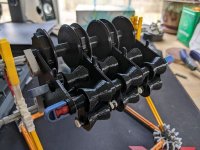
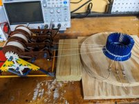
In other news. I rebuilt the wire winder that I showed off a bit ago. I made it larger and easier to use. Its not perfect, but it is a huge help. I keeps everything tight while I wind things. I have only tested with the nylon twine, but the wire is next. I have the litz wire machine all spooled up and ready to go.
PXL_20220823_033542698 small.jpg
 
Back
Top