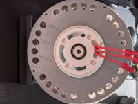
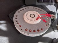
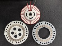
DIY Toroidal Axial Flux PM

Thecoco974 said:
Basicaly in star you have two phases in series, the two phase voltages are added and give line voltage. Beeing 120° appart the sum isn't two time peak phase but Root(3) * Peak phase voltage. kv = Peak line-line voltage/RPM so going from star to Delta increase the kV by a factor of Root(3). Also in Delta when powering a phase there is a leakage current going through the two other phases not contributing to torque and causing inneficiencies.
So in most cases star is choosen with a number of turns giving the wanted speed range.
Switching to Delta only when high speed is needed has been done on this forum I think but wasn't giving good results if I recall.

If you have a good multimetre, probing Line to Line in AC mode could give good results if the frequency isn't outside the input frequency range, but the rectifier trick has allowed me measuring it at low frequency on crazy low kv generators.

Without back Iron is a good first test anyway, validating (or not) the simulation result.
Looking forward to it !

Thanks for this. that is helpful. I will still stay away from using it for now, but I will continue to leave all the wires accessible for if I ever do end up using it. My multimeter is good enough I think.... Its sort of an off brand, but seems to have many functions.

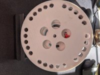
Rotors were all glued up. I smacked the stator into place, and put it together with magnets only
resized-image-Promo (61).jpeg
resized-image-Promo (60).jpeg
resized-image-Promo (58).jpeg
resized-image-Promo (59).jpeg

But unfortunately, this post ends in bad news. One thing that I noticed while putting the magnets into one rotor, was that it bent quite a bit. I assume from the strength of the magnets all pulling together. This really messed with the tolerances. It wouldn't even spin. At first I thought it was my epoxy issue, so I tried to force it to spin, which sort of worked. there was still a lot of friction. So I sprayed it with some Teflon lubricant, and hooked it up to an ESC. I got it to spin, but it pulled a ton of current and got hot in a second. When I removed half the rotor, I realized that it smoothed things out, but in doing so it revealed that not all of my wires were fully in the channels. Also, the amount of current that it pulled or something, pulled the coil ends out of their slot on the hub, which caused even more friction. I have a gear extractor, but I cannot fit it on with the stator in place. So I do not have a good way of removing the stator from the other side of the hub. Also, since I tried to clean up the stator after I had glued it to the hub, I think I ruined its ability to stay in place a bit. It seemed to move around rather freely.

Given all of this.... I have made some modifications to the stator hub and the rotor that was bending. I am still not quite sure why one rotor bent while the other didn't. They appear to be the same thickness, but perhaps different infill pattern or percentage? I'm not sure. I added 1mm to the rotor thickness to help with this. I have to imagine having an iron back on the magnets would help with this too. On the ring shaped rotor, I added a slight chamfer to one side of the inner diameter to help provide a bit more clearance for gooped up epoxy. I modified the Stator hub too to hold the wires better, and I put notches on 120 degrees apart to facilitate using the gear extractor to separate things If I need to in the future. I also modified the stator. I am going to try to go a bit extreme with the overhangs on the inner diameter in hopes that it will provide a flat surface of some kind to epoxy better to the hub. I also slightly moved the position of the wire channels a bit deeper to better hold them on top and bottom.

I think even with the design changes though, there are some concerns. I still do not think that the stator and hub have a solid enough connection. Also don't like that the wires stuck up out of the channels.

I keep talking about a jig, but I think that's what needs to be made to help push the wires into place after winding, and maybe something that could easily be clamped when epoxying the stator to the hub. But, also I am thinking it would make more sense to try to wind all three phases at once as the wires can overlap and more uniformly fall into place (I hope). So I am thinking of some kind of three sectioned spool that would each hold only enough for each phase that I could wrap around easily.

I feel so defeated by the tolerance issue, I should have seen that coming and not put it all together. I got too ambitious. However, I think I learned a lot, and I am ready to try again. I have already printed another rotor with the thicker backing, and the hub will be done momentarily. The ring shaped rotor and the rotor separator are re-usable, and I sanded a chamfer on the ring rotor. I also have an extra stator core that I could use to try playing with if I get too impatient.

Not sure I want to count this last one as mk4 given the lack of success, but there will be another motor soon!
 
Shame. It looked really nice.

Do you have a bearing between the grey outer and white inner? Or is the whole rotor cantilevered from the top?

You can get large diameter thin section bearings if not. They're a bit expensive, but with a design tweak you could probably reduce it to a relatively cheap ~25mm bore bearing.
 
mxlemming said:
Shame. It looked really nice.

Do you have a bearing between the grey outer and white inner? Or is the whole rotor cantilevered from the top?

You can get large diameter thin section bearings if not. They're a bit expensive, but with a design tweak you could probably reduce it to a relatively cheap ~25mm bore bearing.

There is no bearing on the grey rotor, its cantilevered. I have considered trying to put a bearing around the outside diameter of the stator, but I realize those are just too expensive. But I had not really thought of using a slightly larger diameter one... That's definitely a possibility.

There was a plot twist last night, I wanted to share the good news! I was messing with it, and decided to just put all my weight into the hub and play with the flex of the rotor since its bending from all the magnets it seems. And it popped down a bit. and it was spinning freely. I don't fully understand why it wasnt spinning freely if it was further out before, but its sort of working so, cool! Also the other rotor, I can shift to align with the next pole. It does not sit correctly on the spacer, and adds 2mm to the air gap (which would effectively make it 9mm if everything was flat). But it allows it to spin without friction. I will print another ring that is slightly larger until I can get the minimal spacing. I also will be making a proper mounting setup.

I love that there is no cogging with these, it seems fake :)
[youtube]XwwuhpOM_js[/youtube]
 
Nice to see it spin! The measurements were a bit fast to see in the video. What kind of power consumption were you seeing?

Any idea how fast it was spinning? I bet you could make it go fast enough to fly apart.
 
It's so quiet! All you can hear is the commutation of the square wave controller.

I'd love to hear this run with a proper FOC ESC. Bet it would be completely silent, just the whir of air.

Very glad for you that you got it working. Congrats.

What do you plan to do with it once it's complete, perfect? I can't immediately see this propelling your bike or flying...
 
fechter said:
Nice to see it spin! The measurements were a bit fast to see in the video. What kind of power consumption were you seeing?

Any idea how fast it was spinning? I bet you could make it go fast enough to fly apart.

I was barely touching the controller knob. when I was playing with it, I was able to get it to pull about 300mA on the lowest possible setting @ ~16V, so ~5 watts. The battery is fully charged, but no real clue how fast it was spinning, though it seems like it was faster than the last time. However, this has no load so that could have something to do with it. One thing I'm not sure of is how a shorted turn would affect the Kv, I definitely exposed some wire, which means its contacting I'm some places, but if its all part of the same turn, I think it should be "okay".

I bet I could totally make it fly apart. Part of me always wants to push the limits and see if it melts or blows up.


mxlemming said:
It's so quiet! All you can hear is the commutation of the square wave controller.

I'd love to hear this run with a proper FOC ESC. Bet it would be completely silent, just the whir of air.

Very glad for you that you got it working. Congrats.

What do you plan to do with it once it's complete, perfect? I can't immediately see this propelling your bike or flying...

I would love to use a FOC controller on it as well. I bought one a bit ago but it seems to only work on a specific Kv motor. albeit I really don't know much about FOC, though I see there are plenty of threads discussing how it works. Maybe down the road. I'm not sure what I want to do with it. I would really like to make a generator, but the goal would be an e-bike. I'm hoping the rotors with iron backing and some more methodical stator winding, and I think I could get something even more performant.
 
For testing purposes you could just get a cheap VESC clone if you want to try FOC.
It has auto detection of the relevant parameters and runs well in sensorless mode.
I use a flipsky 4.20 and it is fine (and cheap). It wont do high current reliably though. The cheap focer2 is Better and still cheap but requires that you do a bit of work yourself.
 
Vbruun said:
For testing purposes you could just get a cheap VESC clone if you want to try FOC.
It has auto detection of the relevant parameters and runs well in sensorless mode.
I use a flipsky 4.20 and it is fine (and cheap). It wont do high current reliably though. The cheap focer2 is Better and still cheap but requires that you do a bit of work yourself.

I like what I see with the Focer2. I don't have a ton of experience making circuits, but I'm up for the challenge of making it. Ill add that to the never ending list of projects :)


I added the heat-set inserts and printed a small mount for it and added this to my older mount. The mount itself is not the most stable. I am thinking I will rebuild it to facilitate testing a bit better. but as you can see its vibrating a lot, and seems pretty out of balance. I didn't run into this with others. I'm not sure if the prints are bad, or it just really bending from the magnets. Either way, new rotors are printed and I will test those out soon. Also the new stator might actually work out. the overhangs didn't print perfectly, but its good enough, and it fits the hub a bit nicer. I think Mk5 is right around the corner.

One thing I keep noticing, is that the hub when pushed all the way on to the rotor, does not sit parallel, its slightly angled, while not much, it makes the difference of about 1mm at the outer diameter of the stator, which is obviously not ideal. I have noticed this with every print. though I have a suspicion its with the stator hub. not sure how to fix that... a shim of some kind? that would only add thickness...

Also another thing I realized is that I was incorrectly understanding the airgap given the thickness of the spacers, so my estimate is off by 2mm. The current spacer it has on it now is 12mm, which means the air gap should effectively be 10mm, but the bent rotor is making that inaccurate.

Posted another video once I get the stand fixed, Ill film something capturing the stats better.
[youtube]z2_eHCKPGr8[/youtube]
 
HalbachHero said:
Vbruun said:
For testing purposes you could just get a cheap VESC clone if you want to try FOC.
It has auto detection of the relevant parameters and runs well in sensorless mode.
I use a flipsky 4.20 and it is fine (and cheap). It wont do high current reliably though. The cheap focer2 is Better and still cheap but requires that you do a bit of work yourself.

I like what I see with the Focer2. I don't have a ton of experience making circuits, but I'm up for the challenge of making it. Ill add that to the never ending list of projects :)

I have the flipsky. I plugged it in and it worked. Zero issues so far with 60amp phase and 13s (54Vmax). I think they're great for the money, possibly a victim of their own cheapness... I mean what are you going to test something sketchy on, that or your 400 dollar VESC original?

The bonus of the cheap focer is it's designed by one of our forum members Shaman. Probably more power. But more hassle.

Still loving the motor...

Buy yourself a scope and you can probe the phase wires for rpm
 
mxlemming said:
I have the flipsky. I plugged it in and it worked. Zero issues so far with 60amp phase and 13s (54Vmax). I think they're great for the money, possibly a victim of their own cheapness... I mean what are you going to test something sketchy on, that or your 400 dollar VESC original?

The bonus of the cheap focer is it's designed by one of our forum members Shaman. Probably more power. But more hassle.

Still loving the motor...

Buy yourself a scope and you can probe the phase wires for rpm

For the short term I will keep running the hobby ESCs that I have been working with, but I feel them get pretty warm, so I know its only a matter of time before they burn out, I will consider changing the ESC then. The Flipsky is certainly an attractive price point, and probably the next step, but I would still love to make one. If only to say I did. I could also see myself making more than one, further justifying the price.

However, I did just pull the trigger on the scope. I have held off buying one for a while now. But its time. I really want to see the waveform, and other data. Sounds like its going to be about a month for delivery. oof

Until then I am going to work on improving the test stand, and build the Mk5.
 
What scope did you get? I recently upgraded to siglent sds1104x-e and couldn't be more pleased with it considering the price.

Building an esc... Well I've now built about 20, of 5 different designs, and can say without doubt it would have been far less effort and far more cost effective given my salary rate to just buy 20x300$ ESCs.
 
mxlemming said:
What scope did you get? I recently upgraded to siglent sds1104x-e and couldn't be more pleased with it considering the price.

Building an esc... Well I've now built about 20, of 5 different designs, and can say without doubt it would have been far less effort and far more cost effective given my salary rate to just buy 20x300$ ESCs.

I went with a BK Precision 2190e. its a two channel, but wasn't crazy expensive. I'm considering cancelling that order though. A 4 channel for about the same cost is enticing.....

As far as building an ESC goes, I would only do it to say I can. I certainly like the plug and play idea. But I was under the impression a good FOC controller was cost prohibitive, but duh. Should have asked you guys :)

I would still love to make one if it worked, but I would have to rely on a totally accurate BOM and diagram. I am not an expert with EE stuff by any means. (yet)
 
Another easy test is to compare the turning resistance with the phase wires open vs. shorted. A good motor will be very hard to turn when the phase wires are shorted. If you barely get resistance, it's not a good sign.
 
HalbachHero said:
I went with a BK Precision 2190e. its a two channel, but wasn't crazy expensive. I'm considering cancelling that order though. A 4 channel for about the same cost is enticing.....

I think you'll find that's a re badged siglent sds1052. Bk précision are probably supplementing their low end stuff by buying from siglent for contract manufacture.

If they're making you wait a month for it... Cancel and get the latest 4 channel 100mhz direct from siglent.

There are a lot of cheap scopes with bizarrely similar cases and button position.

Siglent is decent for the money. Actually mine easily out performs the similarly specified and same year tektronix 2kusd scope we have at work.
 
mxlemming said:
I think you'll find that's a re badged siglent sds1052. Bk précision are probably supplementing their low end stuff by buying from siglent for contract manufacture.

If they're making you wait a month for it... Cancel and get the latest 4 channel 100mhz direct from siglent.

There are a lot of cheap scopes with bizarrely similar cases and button position.

Siglent is decent for the money. Actually mine easily out performs the similarly specified and same year tektronix 2kusd scope we have at work.

Shoot, good to know. I tried to cancel. go figure it wasn't actually back ordered. and might ship. and since its evening on a Friday... Not much to do now. They said they might be able to catch it before it ships, but. They will be able to return worse case, and ill be buying your recommendation. A bit more money, but I prefer a recommendation over google search results any day.

I have an EE friend that said he would help me learn it. Looking forward to it getting here.


fechter said:
Another easy test is to compare the turning resistance with the phase wires open vs. shorted. A good motor will be very hard to turn when the phase wires are shorted. If you barely get resistance, it's not a good sign.

I have not heard of that/tried it before. I will certainly give it a whirl and report back. thanks!
 
A little late, but I have to congratulate you on getting the newest version to spin! :thumb:
So nice to get some sweet success after all the work you've been doing, and all the problems involved!
I think your closing in fast on this guy,.. 3D printing the parts is a real game changer. :shock:
 
Just catch up with the progress !

Nice to see you got it running ! Congratulations :D

Getting something 3D printed to run true might be a chalenge in itself with all the forces at play but i'm sure you will improve on that on the next build . I know it's hard without a lathe or a cnc mill but you could do a back iron by hand. having a piece of steel in the rotor will surely had rigidity (but also increase the pulling forces).

HalbachHero said:
I like what I see with the Focer2. I don't have a ton of experience making circuits, but I'm up for the challenge of making it. Ill add that to the never ending list of projects

I've build one and if you don't have any experience with smd soldering (like myself) the drv8301 is really a hard thing to solder properly, and if not done right or with a faulty chip it take all the board with it :roll: . But once working right it sure will be a good match to your motor. Coreless need a sinusoidal drive for best efficiency.
 
Thecoco974 said:
I've build one and if you don't have any experience with smd soldering (like myself) the drv8301 is really a hard thing to solder properly, and if not done right or with a faulty chip it take all the board with it :roll: . But once working right it sure will be a good match to your motor. Coreless need a sinusoidal drive for best efficiency.
Yes those things require the right tools to solder properly. I couldn't do it. But you can get a pre-soldered one on a development board for not too much:
https://www.ebay.com/itm/1536556305...GaElMazUXdzNuVITF000pMNRbeo9t8d4aAuu4EALw_wcB
 
APL said:
A little late, but I have to congratulate you on getting the newest version to spin! :thumb:
So nice to get some sweet success after all the work you've been doing, and all the problems involved!
I think your closing in fast on this guy,.. 3D printing the parts is a real game changer. :shock:

Thanks! your post was quite an inspiration to the progress made recently. And yes, certainly nice to see it spin, although, it's not quite as satisfying with this version. the others did not have the balance issue so I could rev them up quite a bit. I think its due to how thin I made everything this time. But 3d printing sure is versatile, and fast if you can make your own designs. I would love to move beyond plastic though.

Thecoco974 said:
Just catch up with the progress !

Nice to see you got it running ! Congratulations :D

Getting something 3D printed to run true might be a chalenge in itself with all the forces at play but i'm sure you will improve on that on the next build . I know it's hard without a lathe or a cnc mill but you could do a back iron by hand. having a piece of steel in the rotor will surely had rigidity (but also increase the pulling forces).

I've build one and if you don't have any experience with smd soldering (like myself) the drv8301 is really a hard thing to solder properly, and if not done right or with a faulty chip it take all the board with it :roll: . But once working right it sure will be a good match to your motor. Coreless need a sinusoidal drive for best efficiency.

Thanks! Yes I am thinking I will have to fabricate the back iron myself. I believe I have all the tools I need to make that work if I am just careful with it.

I will purchase an FOC controller in the near future, and will likely try to make the FOCer down the road, but yeah that chip will present an interesting challenge, maybe Ill practice a bit on other SMD components first :)

Also, a couple questions for the community:
Is there a recommended material for back iron? does it benefit from being laminated layers? Would aluminum around the back iron cause issues? I am feeling pretty good about the rotor design, and given the bending I'm wondering if it would be possible to cnc mill them. There is no super complex geometry involved, and I could likely make it thinner.
Also, is there an easy method for balancing a rotor or more specifically a ring shaped disk?
And does anyone have a good resource for ampacity of copper or even better information on how multiple turns may affect that ampacity, bonus points if it includes information on litz wire.

Thanks all!
 
Ideally you'd find some transformer steel.

Lamination not so important for rotor, since the magnetic field isn't rotating in it's frame.

Balancing is a pain. Best i can think is put magnets on it in places and see if the vibration gets better or worse. Industrially they use jigs with accelerometers. And can monitor the phase and magnitude of the vibration.
 
Back iron is generally low carbon steel. You want something with high saturation. With magnets attached, you can test by seeing if a paper clip sticks to the back side. If the clip is strongly attracted, the iron is saturating, which means you need a thicker piece. Good steel will require the thinnest piece to avoid saturation.

If the back iron is thick enough to avoid saturation, a piece of aluminum behind it should not cause any problem. You don't want any aluminum close to the gap where the flux is changing.

You can attempt to statically balance a rotor by placing the shaft on a pair of level knife edges and seeing where it stops. You can add weights or grind away weight on the opposite side until it has minimal tendency to stop in the same spot. Not as good as dynamically balancing, but something you can DIY and can be pretty close.
 
fechter said:
Yes those things require the right tools to solder properly. I couldn't do it. But you can get a pre-soldered one on a development board for not too much:
https://www.ebay.com/itm/153655630553?c ... u4EALw_wcB

Didn't know about those before ! The limited power stage isn't really helpfull though a drv8301 breackout would be usefull with a modified FOCer board.

HalbachHero said:
And does anyone have a good resource for ampacity of copper or even better information on how multiple turns may affect that ampacity, bonus points if it includes information on litz wire.

You won't find generalised information about that, it really depend on the design, but here are some points I realised when trying to evaluate the power capabilty of my design :

- With coreless design most of the heat come from Joule losses in the coils (assuming fine enough litz wire to cut on eddy current losses). So the power dissipated as heat come down to : P=R*I² . With R calculated as : R=rho*(l/A) , rho = 1.68E-8 ohm/m, l is the phase length in m (time 2 if Y terminated), A is the copper section in m².
- From the above you can see that the more turn the less max power you can get out of your motor since Kt is double each time you double the turn count but R increase 4 time (double the phase lenth and half the copper section each time). Hence we need high rotationnal speed to get high power from coreless.
- Now that you know dissipated power, a thermal analysis of the motor is needed. How much heat is dissipated in the air/conduct elsewhere dictate the max continuous power. Calculation of the thermal inertia of the motor will give peak power for X time

Some information might be incorrect, please correct me if this is the case.

fechter said:
If the back iron is thick enough to avoid saturation, a piece of aluminum behind it should not cause any problem. You don't want any aluminum close to the gap where the flux is changing.

I agree with that, hoverboard motor are cast aluminium on a steel tubing section for the back iron for exemple.
In the case of the ourunner design this not an issue since everything except the stator is immobile in the rotor frame. For inrunner like mine you need to simulate flux "bulging" radially in the airgap and make sure it's not going bridging with the outershell.

fechter said:
You can attempt to statically balance a rotor by placing the shaft on a pair of level knife edges and seeing where it stops. You can add weights or grind away weight on the opposite side until it has minimal tendency to stop in the same spot. Not as good as dynamically balancing, but something you can DIY and can be pretty close.

With this design it can actually be sufficient since the rotor is close to a disk shape. Dynamic balancing is needed when the rotor as a longer axial mass repartition.
 
Sort of on topic,.. I'm always looking for sources for electrical steel, and a while back I found some mega E-I pieces
on Ebay. These things are huge! And you get 25 - 40 lbs of it for a decent price, considering you can't find this stuff
anywhere in small amounts. The dude has several offerings to choose from.

https://www.ebay.com/itm/224229761933?hash=item343522a38d:g:S-EAAOSwmyNfqxzN

The other source is McMasters believe or not. But it's very strange because it comes in .001" and .005" thicknesses.
Almost useless, except it would be easy to cut, and you could stack it or shape it. Didn't look at the price.

https://www.mcmaster.com/steel/electrical-steel/

Not really what your after, I know, but a source is a source, and we need all we can get. Thought i'd post it incase any-
body might be looking for lamination steel.
 
Thanks for all the suggestions. I will have to add the shaft to this motor to balance it the way that was suggested, but after playing around with it a bit, I feel that the issue might not be balance. I think a lot of the vibration is coming from the rotors wobbling. I'm equating this to them bending, but I'm not positive. I looked at online CNC services, I don't think that's going to be an option for the rotor. Unless I plan on buying 100, its not cost effective at all. Maybe I can make a mostly printed CNC? I've always wanted to...

I contacted the company that I bought the thrust bearing washers from. Turns out they were backordered. I specifically bought from them because they were not showing back ordered... oh well. They should be "shipping soon". McMaster is a good source but after pricing things out, its might actually be cheaper and less effort to just buy the washers, but they wont be the right size, and If I want the back iron to also be a mounting point, then I cant just use washers.

I played around with the new stator design, and the litz wire machine. I removed the gear that turns the drum of spool, so I could just run untwisted litz on to a spool and was able to wrap 6 turns of it on the stator and its held in place quite nicely, however I am still worried about the subsequent phases. I am making a spool that will hold the wire needed for 3 phases to turn them all at the same time, who knows it might even save time winding it too.

I spent some time making a spreadsheet with the calculations that theCoco974 provided earlier in the thread.
https://docs.google.com/spreadsheets/d/1sBhVUqrSQ-UtbOS_Dsluh5LSSh5DhSkeStmJ5KxfhIo/edit?usp=sharing
Using the results of the sim measurements, and some other values, a bunch of values will be spit out. I did my best to calculate the power lost to heat, and added in a few other inefficiencies. Its nice to easily see the difference after a slight tweak to the architecture. Amazing what 1mm can do.

Using that spreadsheet, and the numbers I got from running a sim with 6 turns gave me a Kv of ~145. I would have to sacrifice some strands of the litz in order to get more turns, and I worry that will make the phase length too long and have too much of a loss to heat. Damn, faster RPM it is... How do I gear it down say 18:1? I'm sure that's too dramatic, and would have significant efficiency losses involved. Maybe another layer of stator and rotor are needed...

I also spent some time making a better setup for testing and filming. The vibration is hard to fully suppress, but I tried. I also made a 1mm thicker spacer which means that there's an 11mm air gap. because it kept hitting something.... this is basically the same as the Mk3, but with a bit more air cooling. I am still worried it will blow up after one did, so I am keeping my distance and using a plywood barrier for protection. When its spinning slower, I have put my hand near it, and its blowing quite a bit of air out radially, which I would hope equates to it cooling itself. Hard to tell without proper testing.
[youtube]X0EttHB80WA[/youtube]

Just recently I started assembling the rotors for Mk5. These are 1mm thicker, and just after putting the first set of magnets in, its bending again... I wonder if its because I have too many holes in the back of the rotor. Either way, its less than it was and I clamped these ones down, so maybe they cure flat, we will see.
 
I think mxlemmings previous suggestion of having jlcpcb mill the rotors out Glass fiber (circuit board material) is excellent. That material is pretty strong, especially against centrifugal forces.

So I suggest that you go do that!

For gearing, I would love if you designed a hypocycloidal drive. They are pretty efficient and can do 18:1 in one stage
 
Back
Top