DIY Toroidal Axial Flux PM

Vbruun said:
I think mxlemmings previous suggestion of having jlcpcb mill the rotors out Glass fiber (circuit board material) is excellent. That material is pretty strong, especially against centrifugal forces.

So I suggest that you go do that!

For gearing, I would love if you designed a hypocycloidal drive. They are pretty efficient and can do 18:1 in one stage

Unfortunately I am not sure where to begin with converting an STL or STEP file to a gerber file, which is what jlcpcb supports. I would love to get this milled, I'm sure that would solve a lot of issues. It seems the services that offer CNC milling are very expensive, even for the G10 material.

A hypocycloidal drive, besides sounding cool, might be a perfect fit here. Would love to try to make one. Though I feel it makes the most sense if it was a inrunner. I'm not going to completely shift to an inrunner design, but there's certainly a good use case for it....
 
A dynamic balancing rig shouldn't be too hard to 3d print, it can be as simple as flexible mountings and a marker. I've not come across any existing designs but they don't have to be complicated, cancelling resonance could be challenging but you can get around that with variable speed.
 
It's been a busy week. I turned 30. woah. Family and friends visiting. Normal seems to be returning.

Couple updates on the motor though :)

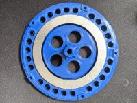
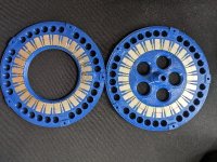
The rotors I made, and started gluing magnets in, were too small for the halbach. So I modified the design. Come to find out, the nozzle on the printer was totally worn out. I re-printed with a new nozzle and it seems fine, even with the small design changes. I also went ahead an ordered some hardened steel nozzles to replace the brass ones I have been using up until now. Also I got the thrust bearing washers in the mail finally, so I decided to include those in the next version. I modified the design to have a slot for the washers. I'm worried they will not really add to the stiffness of things, but we shall see. I also made a little jig for putting in the non-halbach magnets without allowing the glue to spread to the halbach slots. this should help save the time I was spending removing the epoxy from the slots prior to putting the halbach magnets in. I will be printing second rotor tonight, and should have those glued up soon.
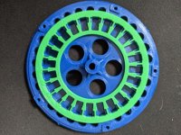
resized-image-Promo (63).jpeg
resized-image-Promo (62).jpeg

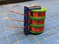
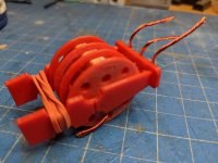
I also made a three layer spool for winding all three phases at once. I made it fit the K'nex and litz wire machine, and removed the gear that made the litz wire machine drum spin, and wound it up. It looked good, but without the twisted litz it has a tendency to get really messy. I am thinking of a sleeve of some kind to slide the three tier spool into to keep the wires in their respective channels. it would make dealing with it easier. Also when winding the stator. Its reallllly difficult to get it started with 60 loose strands of wire everywhere. However, once it was started it was actually quite easy to wind. but eventually I found that the three spools were not identical, and led to differences in length over time, and by the end of the first lap it became impossible to work with, the slack wire constantly twist themselves up.
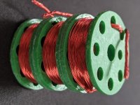
resized-image-Promo (23).jpeg

Made a small tweak to the Hub too, which means that I have essentially needed to re-print every part again. So it goes!

So back to the drawing board for the spool thing or I need another way of working with the three phases at once.

I have really been spending a lot of time thinking about the cycloidal gear. that could really make this a viable thing. I am really interested in trying to make one, but I see it as an inefficient gear, or heavy if you deal with those inefficiencies. I would love to come up with a creative way to not need a bunch of bearings to make it run nicely. I still feel that it would be best applied to an in-runner, but it could be used with my form factor too. Too many ideas, not enough printers.
 
Another small update.

I printed a guide for the tri-spool I made to help the wires to stay in place instead of unraveling and crossing over one another. when its untwisted.

I also removed all the wire from the litz wire machine. One spool was nearing its end, so the others were close. But I took some time to sand things down so it would turn a bit more smoothly. Some of the spools were getting snagged on burrs either on the spool or the carrier. Also, some of the spools had such bad layer adhesion so they were splitting. I modified the design slightly, and re-printed the spools. I will re-run wire some wire soon, and get the tri-spool re-spun too.

Once I get that done I can make another attempt at the stator. Also during all of this I printed 3 stators (which take about 8 hours each). Only to have them break trying to get them off the print bed. A hard lesson of improper leveling, but I finally got another one. I may try to get ahead and print a few before I need them. Just too much stuff to print...

On the rotor front, I was able to get things glued up, and it looks good. I am seeing 0 bending. It's very apparent that the iron is significantly improving the flux leakage out of the back. I played with the rotor between gluing the first set of magnets and the halbach magnets in. using thin screwdriver on the back. while the iron does a lot, it does not prevent all of it, but adding the halbach does in fact help. However, comparing a non-iron backed halbach rotor, to the iron backed non-halbach rotor. The 1.5mm of iron (which does not cover the entire back face of the magnets), is doing more to prevent flux leakage. Combined however, and nearly no flux is leaking through. It's I tried the paperclip method too, it does still hold the paperclip, but barely. So possibly a thicker iron back is in order. Or one that completely covers the back of the magnets. With everything epoxied in place it looks solid, and flat. No magnets popping out. I'm feeling good about this one.
resized-image-Promo (64).jpeg
 
Looking good ! Good to know the back iron help with the rigidity :thumb:
The previous stator was too damaged to be reused with this rotor ?

Just started my own thread to share my build without poluting yours :

https://endless-sphere.com/forums/viewtopic.php?f=30&t=112172
 
APL said:
Rotors are looking awesome! :thumb:

Thanks!

Thecoco974 said:
Looking good ! Good to know the back iron help with the rigidity :thumb:
The previous stator was too damaged to be reused with this rotor ?

Just started my own thread to share my build without poluting yours :

https://endless-sphere.com/forums/viewtopic.php?f=30&t=112172

Yes, im very happy it helps with the rigidity. The previous stator was a little damaged, but its also an issue of the removing the stator from the rotor. the newer versions of the hub have notches for a gear extractor to help separate things. Without that I have to rely on the heat set inserts to hold the hub while I knock the rotor out.

I may attempt to re-use the stator, but I also like the idea of creating a collection of the versions instead of frankensteining them :)

It's awesome to see another motor thread. I'm excited to follow along!


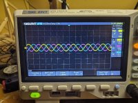
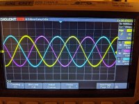
I got the scope today. I couldn't wait, I had to see the waveform. This is the back emf from just spinning by hand. It's beautiful
resized-image-Promo (65).jpeg
 
HalbachHero said:
I got the scope today. I couldn't wait, I had to see the waveform. This is the back emf from just spinning by hand. It's beautiful
resized-image-Promo (65).jpeg

Oh that's quite special. Really quite pleasing.

How did you connect the ground? Resistor centre tap?

What do you think of the scope? I'm loving mine.
 
mxlemming said:
HalbachHero said:
I got the scope today. I couldn't wait, I had to see the waveform. This is the back emf from just spinning by hand. It's beautiful
resized-image-Promo (65).jpeg

Oh that's quite special. Really quite pleasing.

How did you connect the ground? Resistor centre tap?

What do you think of the scope? I'm loving mine.

You will have to forgive my ignorance. I know very little about how to use a scope. I did not need to ground anything. I simply hooked one channel up to each phase wire and spun the motor by hand. I also did use the ground clips to short the phases together as was suggested in an earlier post. It certainly made the motor not want to spin, but it was not hard to spin.

I've been lagging with getting the next stator done. I need to re-spool the litz wire machine. and I'm trying to get footage of my work and I'm an amateur so its been a bit slower getting anything done. I changed the spools for the machine, but that resulted in needing to print a few more things, but I think I'm ready now. New stator soon-ish?

I put the rotors together with a spacer. Its solid, still no bending, but it certainly will weight more. The rotors alone are now 260g. The washers added about 60g. I suspect that in total it will weigh ~400g if I can squeeze a few extra turns in the stator.
 
mxlemming said:
What do you think of the scope? I'm loving mine.

Oh yeah, the scope is really nice! everything has a nice feel to it, and it certainly seems well constructed. The display is bright and clear. Other than that, I don't have much experience with them, but this is lightyears ahead of some of the older ones my grandfather has.

I did find out that these are the same brand as my EE friend has at work, and the same exact one that we have at my work. Through that was a neat coincidence. Thanks again for the suggestion.
 
I want one. Mine still has a vacuum tube and weighs enough to anchor a ship. I have an expensive Fluke Scopemeter at work and I'm not super impressed with it.
 
HalbachHero said:
You will have to forgive my ignorance. I know very little about how to use a scope. I did not need to ground anything. I simply hooked one channel up to each phase wire and spun the motor by hand. I also did use the ground clips to short the phases together as was suggested in an earlier post. It certainly made the motor not want to spin, but it was not hard to spin.

Aaah

This is fine, as long as there is minimal noise. The scope has a weak pull to ground, so it implicitly created it's own ground. Your results are perfectly valid, but if you try to do this while running the motor, you will probably be disappointed.

If you are new to scoping... they are generally pretty robust, but think very carefully about where you attach the ground clips. The probes are high impedance, basically can attach them to anything (within reason), but the ground connection is not. If you accidentally connect the ground clips in the wrong place, it can do anything from nothing to causing resets to creating lots of noise to... Shorting your lipo battery through the scope with ruined scope/probe leads/battery fire as a consequence.

Keep hold of the little ground springs and accessories that came with it, very useful for probing little components and reducing noise etc.

On that note, are you still driving everything direct from the battery? If so, consider not doing that, and buy a DPS5020, DPS5005... something from that series... which gives you a really really fast, accurate current limiter. You can power them from a battery.

Your motor seems to have ~12.5ms per sin wave and 1.2V peak to peak, 12pole pairs. In RC world this would be 1000/12.5*60/12 = 400rpm. This I think means you have ~330kV motor, allowing for reading off screen guesses and sinusoidalness (RC models usually square, so nota direct comparison) which I guess is pretty good for the size.

Any idea what the phase resistance and inductances are yet? Got the VESC to measure it?

fechter said:
I want one.
Code:
Occupation:Engineer
Location:California Bay Area, USA
So... buy one. Engineer in Cal bay area can afford a scope ;)
 
mxlemming said:
If you are new to scoping... they are generally pretty robust, but think very carefully about where you attach the ground clips. The probes are high impedance, basically can attach them to anything (within reason), but the ground connection is not. If you accidentally connect the ground clips in the wrong place, it can do anything from nothing to causing resets to creating lots of noise to... Shorting your lipo battery through the scope with ruined scope/probe leads/battery fire as a consequence.

Keep hold of the little ground springs and accessories that came with it, very useful for probing little components and reducing noise etc.

On that note, are you still driving everything direct from the battery? If so, consider not doing that, and buy a DPS5020, DPS5005... something from that series... which gives you a really really fast, accurate current limiter. You can power them from a battery.

Thanks for the advice. I read enough before hand to understand the risks of improper grounding. I will definitely keep that in mind, and for sure I will keep all the little pieces it came with. I look forward to learning it.

I am driving things from the a lipo battery still. Considering getting a power supply so that I can more easily play with voltage, but the lipo works for now. I will definitely get that current limiter. I always thought there should be something like that in place. or at the very least a fuse. There's always going to be a weakest link, but I did not know about that product. Another great suggestion thanks!

mxlemming said:
Your motor seems to have ~12.5ms per sin wave and 1.2V peak to peak, 12pole pairs. In RC world this would be 1000/12.5*60/12 = 400rpm. This I think means you have ~330kV motor, allowing for reading off screen guesses and sinusoidalness (RC models usually square, so nota direct comparison) which I guess is pretty good for the size.

Any idea what the phase resistance and inductances are yet? Got the VESC to measure it?

Can I ask where you got that formula from? The 330Kv sounds accurate given some rudimentary calculations I based on the tachometer readings. But I would love to get a more accurate number. Also that's with a large air gap, and no iron in the rotors. I would really like to see how changing those factors affects the Kv. Also that seems like a reasonable performance metric to look for given some parameters staying the same. I think torque constant would be as well.

I only have the hobby ESC. the VESC was going to wait, as the scope was a bit pricey, but I also have very little self-control. So we will see :)

I would love to drive this with a FOC controller of some kind now that I have actually seen the waveform. This is also a subject I would love to learn more about. I understand the concept at a basic level, and I have read parts of the thread related to this subject, but I do have some specific questions.
Given that I have a sinusoidal back EMF, is it reasonable to assume that a sinusoial commutation such as an FOC controller, would more efficiently drive my motor? How would this impact Kv or Kt?
Also, might I need hall sensors for FOC to work properly?
 
FOC should be better with that nice sinusoidal profile.

Don't need hall sensors. Sensorless can be done with FOC, VESC has a sensorless observer which generally works better than the hall sensors for VESC.

I have no formula. I'm just dividing the rpm shown by your scope (says it in Hz...) By the number of pole pairs to convert from electric to mechanical and x60 for seconds vs minutes then eyeballing your voltages on the scope and seeing about 1.3V.

Kv is rpm/V so ^^

Kv and Kt are fundamentally linked, one and the same but convert the units.

FOC won't change the Kv but it works differently so if set up right you'll get more dynamic range (faster) and it should be quieter. Should be able to get a bit more torque for the same power. Don't expect mega improvements, it's a few% not 2x

Edit:
http://learningrc.com/motor-kv/
This explains kt kv relation. Easier than typing it out.
 
mxlemming said:
FOC should be better with that nice sinusoidal profile.

Don't need hall sensors. Sensorless can be done with FOC, VESC has a sensorless observer which generally works better than the hall sensors for VESC.

I have no formula. I'm just dividing the rpm shown by your scope (says it in Hz...) By the number of pole pairs to convert from electric to mechanical and x60 for seconds vs minutes then eyeballing your voltages on the scope and seeing about 1.3V.

Kv is rpm/V so ^^

Kv and Kt are fundamentally linked, one and the same but convert the units.

FOC won't change the Kv but it works differently so if set up right you'll get more dynamic range (faster) and it should be quieter. Should be able to get a bit more torque for the same power. Don't expect mega improvements, it's a few% not 2x

Edit:
http://learningrc.com/motor-kv/
This explains kt kv relation. Easier than typing it out.

Good to know I wont need sensors, my hope is to keep things as simple as possible.

Thanks for explaining. I should have been able to figure that one out... and thanks for the link, that does a good job of explaining things. Ill bookmark that one


I was able to get the litz wire machine re-spooled, and wound the tri spool up again. and attached a wire guide I printed to help keep things from getting too tangled.
resized-image-Promo (67).jpeg

This was working pretty well, but I still managed to tangle the wires in a way that doesn't seem possible... I must have crossed them at some point. I also used the solder pot to solder the ends of the three phases together before I started winding.
I thought this would be helpful, but quickly realized that it would be impossible to do subsequent laps. And about a 1/4 of the way around the first lap, I snapped the stator. ugh. Its just too thin on the inner diameter between each wire channel. I modified the model slightly to have a teardrop shaped channel in hopes of maximizing the material between each channel.
resized-image-Promo (68).jpeg

I wonder if it would be worth making a mold that I could then use to make a stator completely out of resin. Though even that might be too brittle with the tolerances I'm working with.

I'm printing this in PLA to get them done quicker who knows I might make use it if it winds up nicely. PLA is a bit stiffer than PETG, but it will not handle heat well which I think will ultimately be a PLA motors demise, but it prints a lot faster, so its good to even more rapidly prototype with.

I also think I need a more clever solution for the wire management on the tri-spool. It might also have something to do with the amount of wire I put on the spools, but its still loosening and ultimately skipping into the other spools and getting tangled to a degree. I think I have a few ideas.
 
The weather has been warm, and there has been plenty to do lately. I have been trying to work on this project where I can, but I have not made a ton of progress lately.

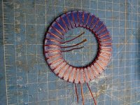
I modified the design of the stator as I showed in the last post. This worked well with PLA. It was far more tolerant to breaking. So I printed some out of PETG. Since I didn't have other parts to print, so I just kept printing them. I have 5 at the moment. I found that I have a file that fits as perfectly as it could into the wire slots which works really well for deburring them. Sanding them down went well. I could tell I don't have to be as gentle with this design even with the PETG. Also using a short length of wire I simulated the 6 turns fitting into a slot. and there almost seems like there is extra room.

I also modified the tri-spool, with some clips that would keep it from freely spinning and loosening the wrap on the spool. I made it a bit smaller too so that it was easer to work with inside the stator inner diameter. Unfortunately the design was too fragile and the clips broke off as I went, and the smaller size turned out to be a bad choice because there was no way I could fit all the wire I needed to on it.

resized-image-Promo (70).jpeg

I was able to get 2 1/4 laps around the the stator before I ran out of wire. But I have faith in this stator design, and I think I will be able to get 6 full turns on it once I figure out the proper way to wind it. Given the experience I had with the tri-spool, I am going to try something different. I am thinking three separate spools but still winding all three phases at once. I just need to be able to keep the wire on the spool from loosening up during each rotation. So I am imagining a way to clip the spools and the stator into something where I can keep tension on everything and work on one phase at a time while the other two stay in tension.

resized-image-Promo (69).jpeg
 
Have you considered using aluminum or copper coated aluminum wire?

It could potentially make your motor lighter. I believe the main reason it was not used in normal electric motors is because of core losses, and since yours is coreless, it might work.
 
There are a number of reasons you don't see aluminum wire used in motors. The main one is higher resistance, so higher resistance losses. Terminating the wire is another problem, as you can't solder to aluminum easily.
 
Xoon said:
Have you considered using aluminum or copper coated aluminum wire?

As fechter mentioned there are a few reasons why aluminum wire is not ideal. another reason is that given that the wire is about 25% of the mass of my entire motor, to me, the mass savings would not be worth the downsides of working with aluminum.


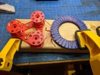
I made a bit more slow progress. I made a tool to help hold the wire spools in place while I wound the stator. I also attempted to make something to hold the stator in place so that I could focus on just the wires, but I can't come up with a clever solution. For now I held it manually and wound the wires around doing all phases at once but one leg at a time. I have only done one lap so far, as I did it last night and was not expecting it to take so long. The first lap around took nearly 45 minutes and that's where I stopped for the night.
resized-image-Promo (71).jpeg

Thinking about it some more, It seems that if I could hold everything in a vertical fashion I could work on both sides of the stator easier. The other thought is to go all the way around with a single phase without overlapping another, then do the same with the other phases. This might make it quicker to wind as it wouldn't involve picking up and putting down the spools repeatedly. Some combination of those ideas might be best.

It's getting there.
 
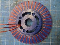
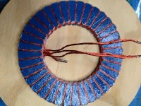
I was able to finish winding the stator last night. I found that it was quicker to go all the way around with one phase at a time. While I was not able to get the 6 that I was hoping for. I used some superglue to hold things in place on the last lap. I did get 5, which is the most turns, and this will end up being the thinnest motor so far due to the rotors being stiffer. The strange thing is, I could easily fit 2 more laps in each wire channel, but the end turns pile up and are too tight to push down at the end. If I used a larger flange on the inner and outer edges, I may be able to snag a few extra turns, but the overhangs are already pretty intense, and are so thin that some broke off in the process of winding it.

I'll have to come up with something the provides some relief from the turns before it enters the channel like a rounded inner and outer diameter. But obviously that will make the wire longer and add a bit of waste.

Either way. It's almost there. I dry fit everything together for now, but I'll epoxy it soon. She'll be spinning in no time.
resized-image-Promo (72).jpeg
resized-image-Promo (73).jpeg
 
I was excited about the progress, so I got up early and glued the stator. I rand a bead of epoxy down each leg on both sides. I then wiped the excess off working it into the voids where I could. I clamped this down with plastic covering things this time. (thanks for that tip :wink: ). Meanwhile I added the heat-set inserts to the hub and sanded down the outer diameter of it in preparation of gluing it to the stator.
resized-image-Promo (74).jpeg

After the stator cured. I added epoxy to the inner diameter of the stator, ran the wires into the hub, and pushed the hub into place. Put the plastic back on it and clamped it down again.

Just a few more hours and I can give it a test spin!
 
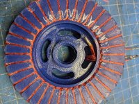
There it is Mk5 in all its glory.
resized-image-Promo (75).jpeg

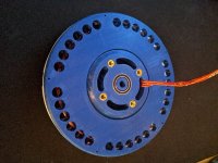
I still need to add the heat shrink to the wires and get the heat set inserts in the rotors, but it spins!
There are two issues with it. 1) It is dragging on one face of the stator. I am not sure if its due the anomalies in the rotor or stator fade, or if something is bending slightly, but it's not dragging by much. I will attempt to space that out a bit, but I'm not sure what would be best given how small the spot is to add a spacer. I could always make another rotor.... 2) The hub sort of loosely fits on the rotor. There is a very small amount of play, that might be even harder to fix, so I may consider making at least one more rotor.

The cool thing is now that the rotors and stator are not bending in this version, there is way more clearance on one side of the stator, meaning I could make a thinner spacer. I might be able to lose as much as 1.5mm of air gap. Currently the rotors are 20mm thick, and the hub only sticks out another 3mm from there. And the entire thing weighs 385g

I'll spend some time soon getting some numbers on it if I can stop it from dragging. Its clear that its suffering from imbalance too, so I will need to try to solve that as well. from the test spin I did on it, its clear it spinning slower with the same battery, which is exactly what I was hoping for. Can't wait to see what this one can do!
 
There are definitely some tolerance issues with the rotor and the hub, but I found that if I spin it in one direction it seems to find a balance in the center. Spinning the other way however, it seems to find its way to one side. Not quite sure what to make of that. Either way. I was able to spin it up a bit. It does vibrate a bit though which still makes me cautious to spin it too fast. If I get some nice weather this weekend, I'll let it rip outside and see what happens.

I also hooked this up to the scope and spun it by hand again. Took this photo which I think reveals some improvement.
resized-image-Promo (76).jpeg

with a frequency of ~36 and a peak to peak V of ~0.75 and my math is correct
36Hz * 60 / 12 = 180RPM
180 / 0.75V = 240RPM/V
That would be a nice improvement

I also see room for improving tolerances and I can remove at least 1mm from the spacer, which will hopefully squeeze out just a bit more out of this same version. I'm not sure if I will need to make a new rotor or not, but I think this is the best one yet, even in its current state. I think the next steps are to balance it as best I can

Oh and heres a video of it spinning
[youtube]VypQxds2Fro[/youtube]
 
Back
Top