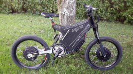
Doctorbass 2WD ADAPTTO / NYX / MXUS 32kW 105 pounds

ridethelightning said:
staying cool at nearly 20kw is a surprise.

perhaps for longer periods it will get a little warmer.

iv also been impressed with how little heat the max-e will produce, even when climbing long hills at high power.

Yeah i agree! the fets used are half the resistance of the 4110 so they produce 1/4 of the heat the 4110 does.. plus the 4468 from the Adaptto have like 3 time more effective surface in contact with the heatsink bar.

I recall i'm driving a 3T hub motor rated 3kW with 19kW 228A batt and 350A phase for about 500Wh in short time ( high average power) and the controlelr REMAIN cold !!! :twisted: 8) I think that the only few people that said their adaptto get warm is because the setting are not perfectly tuned :p

We will agree that i'm using the worst conditions: high speed winding ( low inductance), high voltage battery (86V) and high power and phase current.. But that beast remain cold.. oh ... sorry.. THOSE BEAST!! i have two !! and BOTH remain cold even if i'm doing 0-60mph in less than 6 sec not perfectly tuned and still using locked firmware!

Now my worrie if magnet demagnetization :shock: the magnetic field must be so high than how these magnets can hold that ?..... what is their limit....

Doc
 
Doc,

How are you able to get so much higher current than the Adaptto allows? Did you get a special version? Also, where can I get some of those batteries that have no sag from their fresh off the charger voltage?
 
congrates to this bike. Kudos!


about these 20kw (or 228A batt) are you sure it is really only the rear controller and not both together? Normally we should see total watts which would make sense. I have 2WD mini-e setup but have not set it up yet.
If 20kW would flow only into ONE motor it would get toasted in no time and i can't believe adaptto has almost 90A overshoot. What temp do you see and to what motor it belongs? (i believe the temp of the hottest motor should be shown, at least this also would make sense)

With two motors the efficiency will be MUCH better during acceleration, so 20kW may feel more insane as you expected :) Take care Doc!
 
John in CR said:
Doc,

How are you able to get so much higher current than the Adaptto allows? Did you get a special version? Also, where can I get some of those batteries that have no sag from their fresh off the charger voltage?

This is the 10kW version :mrgreen: not the 14, but i have modified it with better and lower RI small and big caps on the bus DC rail. I have the 14kW version too but not installed them yet ! Adaptto mentionned these 14kW can also do 20kW easy when unlocked.

I dont know whi my still locked versio controller did so high power but i was really surprized to see 228A on the display while accelerating!

The motor reached max 98 degree C during these couple acceleration run,

I will do more test soon as well.. but here the sunset is happening at about 18h and i dinfinish at work at 17h30.. so there is very low margin for test during the week. :(

The battery i am still using are the Farasis 25Ah cells, same as Zero use. Luke said these can do up to 400A between 80-100 SOC. and that the max current depend on teh SOC as well.. thst'a probably because of the 3.0V limit and RI... But i am using 6 gage wire and SB50 connector and bullet 150A connection on each controller. I could go with gauge 4 or 2 as well. i'll see.

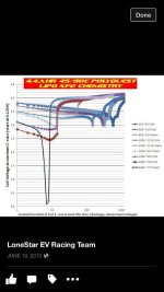
I am finishing my 13 pounds 70kW lipo now and will stop the torture to my great Farasis cells and will connect this awsome Lonestar Lipo drag racing battery soon! that will save 25 pounds and move from the actual 33miliohm 25Ah of the Farasis to the incredible 13 miliohm/9Ah lipo pack !! Sag will reduce by huge factor !! ands that's at ambiant temp!! John Metric measured them at 70 celsius for fdrag racing max performance and lower the RI by about 40% witch would mean about 8 miliohm for the full pack !!

I attached the previous lower performance lipo graph he was using before swaping with these new unclasified from military lipo that i got from him
 

Attachments

  • 11872604_944161805626910_1148293209_n (Personnalisé).jpg
    11872604_944161805626910_1148293209_n (Personnalisé).jpg
    37.3 KB · Views: 3,842
  • 11920501_944162062293551_906155741_n (Personnalisé).jpg
    11920501_944162062293551_906155741_n (Personnalisé).jpg
    36.6 KB · Views: 3,842
madin88 said:
congrates to this bike. Kudos!


about these 20kw (or 228A batt) are you sure it is really only the rear controller and not both together? Normally we should see total watts which would make sense. I have 2WD mini-e setup but have not set it up yet.
If 20kW would flow only into ONE motor it would get toasted in no time and i can't believe adaptto has almost 90A overshoot. What temp do you see and to what motor it belongs? (i believe the temp of the hottest motor should be shown, at least this also would make sense)

With two motors the efficiency will be MUCH better during acceleration, so 20kW may feel more insane as you expected :) Take care Doc!


I know it is hard to believe but Adaptto confirmed to me that the display only show data from ONE controller! :shock:

Yes these little 10 gauge DC input silicon wires got 228A... I tested them at 100A and these hold that current very well so i dont worrie too much with the 228% higher current.. these wire only dissipate like 5 time more heat.. :lol:


Now i really want to show you these result in real time guys.. my main problem is the time window to do these test and finding a great way to film that while i drive the bike!! Anyone have some free time to go in Quebec helping me for the camera shooting :lol: ?.. it's a very "warm" 10 celsius outdoor these days :roll:

Doc
 
Alex's hit and stayed right at 160A, which I take is the newer program limit, since their documentation says 140A peak battery side. That's why I was wondering what's special about yours. If they're good up to your 228A battery side, then I'm much more interested than if the limit is 160A.

Hopefully you really are getting that kind of power into the motor, since it puts extra pressure on me to continue my weight loss. I'm down 55lbs (25kg) now, so only 40 more to hit my lowest target. Image your 2 Adaptto's pouring current into a higher efficiency load without the traction issues like you'll have up front. :twisted:
 
John you can unlock the controller and have it unlimited, but you loose the warranty. But whoever though about warranty when modding a 18-24FET controllers right? :) Just unlock it and go for a ride at 250A, who know maybe it will survive.
 
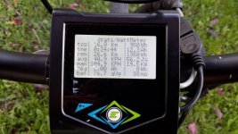
Here is the shot i took after the ride for the max power recorded. When i saw that i decided to take a closer look to the batt amo monitor while i accelerate and when i was that 227-228A constant during acceleration this concluded that the 19.5kW is real! :twisted:

I have a AC/DC true RMS FLUKE 337 clamp meter. I will install it on one of the phase and we will see how much amp!! as wellas for the batt amp :wink:

I just measured the exact weight of the bike with the long range Farasis 1.8kWh battery :

Rear: 62 pounds
Front: 72 pounds

Total: 134 pounds

The actual battery weight 33 pounds and the battery weight 13 pounds

By replacing the battery the bike will drop to 114 pounds.

Doc


Doc
 

Attachments

  • 20151004_174515 (Personnalisé).jpg
    20151004_174515 (Personnalisé).jpg
    101.4 KB · Views: 3,782
  • 20151004_174322 (Personnalisé) (2).jpg
    20151004_174322 (Personnalisé) (2).jpg
    188.7 KB · Views: 3,782
Stielz said:
This is still on locked firmware :!: :?:

How are you managing to get the current this high?


I dont know.. :lol: i'm touching wood..i guess....


I will definitively have to doublecheck that soon!


Doc
 
Nice build Doc!
 
liveforphysics said:
Nice build Doc!


Thanks Luke!.. That was alot of work and customization !!

btw i'm going to send you your Adaptto this week :wink: i'm impatent to see your build too! :mrgreen:

Doc
 
Doctorbass said:
I know it is hard to believe but Adaptto confirmed to me that the display only show data from ONE controller! :shock:

Yes these little 10 gauge DC input silicon wires got 228A... I tested them at 100A and these hold that current very well so i dont worrie too much with the 228% higher current.. these wire only dissipate like 5 time more heat.. :lol:

if we really only see amps and watts of one controller, how we ever will have accurate SOC and consumption values? I'm really pissed off to hear that since i'm going to install my 2WD adaptto system soon to a rickshaw for a customer and i thought this was evident.
two years now since release and still frocking beta software :(
I will make a post about these bugs in adaptto thread with large text and colours, but personally i have no more hope to get a firmware without these issues.
I have contacted adaptto already many month ago and they say there is no more memory left in the controller brainchip for improvements and instead of trying to fix these bugs the engineers and programmers focus on newer products..
they said the bugs probably can be fixed, but it would take lots of time for re-programming etc. :(

about the current overshoot: may it be that this high current is extremely short peak only the controller sees and stores in consumtion screen, or does the display show it on main screen at least for a few seconds during acceleration?
Please keep your eyes on the street and not on the display during such hard acceleration. Like you mentioned in pm you really should install the smart phone holder oder a cam focused on the display and watch it later (like Allex did)
 
Best is when you film when the sun goes down, you see the display values much better. Mounting is easy to do, something like this
file.php
 
Martin:
Yes the 228A current was sustained during acceleration.. just like the 140A most common max batt amp people see. I know Jeka is working hard to iproobe the actual Platform. but i agree with you that 2WD does not Worth it if the SOC is calculated from the Master controller only...almost if slave and master are set to different power!.. in that case it is nearly impossible to evaluate the consumption of both!


Allex:
Yeah Duck tape!! 8) It solve nearly everything!

The goal with the camera is to see the road and the speed( best is GPS and both adaptto shown) and power level.

i will figure out a way to do that.

Doc
 
My Analogger w/ GPS will document videoed run(s)...I need to learn how to use it first...not a gadget guy. My CA3 gets the timing for speed and distance from one controller (no way a GPS is sufficiently accurate except for average speed over significant distance..."GPS certified" always cracks me up). Current info comes from a stand alone high current shunt to which both controllers are connected in parallel. I'll make the boys figure how to do the overlay dashboard for videos. That should be a good project to help push them to doing something useful with technology instead of only gaming, messaging, Facebook, etc. Any input on how to help kids stop or at least curb the useless "button pushing" is welcome.

For legal reasons I want to avoid using a public road for well documented runs, and the newly rejuvenated racing and entertainment complex just 5 miles away would be great for electric racing, which would tie in well with CR's eco-tourism and goal to become the first carbon neutral country by 2021.

For the 1/4 mile I need to get over to the track during a practice session to see how comfortable I am with only a 200m shutdown distance. They set it up on the main track's longest straight of only 600m. I also need to see how much speed I can carry through the curve leading into that straight to see if a top speed run makes any sense. My previous best was at 700-800m, though I weighed a lot more, used my daily rider controller tuning, and didn't jump on the throttle.
 
Allex said:
Looks like SOC is calculated from both controllers(unless it is two separate batteries) but power level is seen from the master only.


Allex, SOC is calculated using the internal shunt and the voltage sensing right? If SOC can be calculated from the total of both controller, it mean that the communication between teh master and slave can be computed right?..

and Power monitoring use the same signal too too... so how could the SOC be calculated but NOT the power level? :|

Doc
 
Let's see the beast do a hill climb in the dirt!

A simple way to check if the adaptto is measuring 1 or 2 is to disconnect 1 :)
 
izeman said:
@john: gps measured speed is not always a bad thing. latest gps modules have a 10hz update frequency. so at 100km/h every 2.8m which is not much worse than a magnet pick up on a 29" wheel.

Speed pickup on the wheel depend on an important factor: the tire pressure and the crip tichness that change over the time... It will influence magnetic pickup type as well as the measurement from the motor pole. But once it depend on the rubber you use that can change few % the radius.

GPS is not affected by that. I checked and there is 20hz GPS tracking speed on the market... Many lan speed record use GPS and some use known distance traveled by a given time.

Doc
 
Unless you have a high precision GPS, which are still pretty expensive, then you can't make the precision claims. My Garmin sure isn't. Yes, anything calculating speeds based on wheel rpm needs an accurate wheel size, and shame on anyone making speed claims that way if they don't make sure that the wheel circumference in the calculation is accurate and err on the conservative side.
 
John in CR said:
Unless you have a high precision GPS, which are still pretty expensive, then you can't make the precision claims. My Garmin sure isn't. Yes, anything calculating speeds based on wheel rpm needs an accurate wheel size, and shame on anyone making speed claims that way if they don't make sure that the wheel circumference in the calculation is accurate and err on the conservative side.


...And... make sure that the wheel radius is measured when you sit on the bike!

My wife think i do too much on these ebike when i ask her to measure the radius of the wheel with me sitting on the bike...


Doc
 
Doctorbass said:
John in CR said:
Unless you have a high precision GPS, which are still pretty expensive, then you can't make the precision claims. My Garmin sure isn't. Yes, anything calculating speeds based on wheel rpm needs an accurate wheel size, and shame on anyone making speed claims that way if they don't make sure that the wheel circumference in the calculation is accurate and err on the conservative side.

...And... make sure that the wheel radius is measured when you sit on the bike!

My wife think i do too much on these ebike when i ask her to measure the radius of the wheel with me sitting on the bike...

Doc

Mine goes fast enough that the circumference grows due to centrifugal force on the tire, so just sitting on it doesn't give an accurate figure either. It seems like trying to measure radius wouldn't net a very accurate result, since circumference would be off by over 6X any measurement error. I prefer to find a flat surface and with a helper sitting on it roll it out in a straight line several exact tire revolutions, measure, and calculate. Differences in tire circumference from slight differences in pressure, centrifugal force, etc are insignificant (well under 1%) compared to the inaccuracy of common GPS's, which can be meters off for the distance from one point to the next.

Maybe Doc will set a high enough number that I pull out all the stops instead of running with my daily rider settings. ie crank up the current and try the greater than 100% speed settings, something I've never tried on any ebike. :mrgreen:
 
I have made a short compilation of most of the tuning settings instruction i am using on the Adaptto:

Here it is step by step:

Note1: you will need to recalibrate above values when when volting up or down on your bike.
Note2: Both manual and auto tuning should be done at the charge state that you are riding in mostly. So don't do it on a fully charged battery nor on a discharged one.

1: Set OVS (fielf weakening) to 0

2: Do a THROTTLE CALIBRATION (thr linear)

3: Lift up the wheel accelerate to 10-15km/h and holding this speed, adjust your ANGLE CORR so you have a smooth rotation.
If the angle is wrong you will hear it and also the wheel will turn more slowly. So keep adjusting it until you have the most silent spin at this speed.
You can also test it on a very long stretch. Find a flat road and drive 15km/h and try and finally keep setting you get the lowest possible temp.
(Angle corr setting compensate for the inaccuracy of the Hall sensors installed. This inaccuracy is the difference between the applied magnetic field of the stator and the Hall sensor angle readings. Since three Hall sensors are installed, this setting is the average deviation of the three gauges from zero. The Deviation of each individual hall sensor is determined and automatically compensated during the motor auto-detect process.)

4: Same goes with IND TIMING. But this time you need to have a constant cruising speed (ex ~35-50km/h). If you do not know what the cruising speed of the motor, then look at"debug" screen, In the line "OA: xxxx DA = xxxx Axxxx" see "Axxxx". Look at the first digit after the letter "A" and gradually speed up motor. It will begin to change in the following order: 8,9, A, B, C, D, E, F. Accordingly, 8 corresponds to the minimum rotation, and F to the maximum. You need a speed corresponding to the letter "D". After reaching motor cruising speed start changing parameter "ind timing". Select a value where the cruising speed is achieved with minimal effort (ie, the minimum throttle). If the wheel does not spin or vice versa spins very quickly, ind timing is off. Very high speed is not valuable. Keep current consumption at no more than 7.5 amps. Under strong throttle, settings above certain values will make the motor begin to slow and get noisy. This should be avoided, reduce the throttle input. Value generally should be slightly less than the threshold at which the motor begins to slow and get noisy.
(Ind timing sets the delay compensation between the signal hall sensor and the control signal of the controller. When rotating at high speeds, the signal from the sensors has been delayed, so you need to adjust the timing. Accordingly, it is the sum of the controller Hall sensor filter circuit delay and the controller CPU processing time. Determined automatically during the motor auto-detect process.)

5. Adjust POWER TIMING so you have maximum torque when you go WOT from 50km/h(about 1/2 of your top speed).(usually values: 0.17 for high-speed motors, 0.3-0.5 for average and 0.7-1.2 for slow motors). PWR timing sets the lead angle shift in relation to the phase current. The greater the inductance of the windings of the motor is, the stronger the control signal phase currents. This setting compensates BEMF.

6: Set OVS timing( field weakening), Optimal values are usually 2-4. OVS timing setting responsible for extra motor speed when the battery voltage is not high enough to achieve the maximum vehicle speed. When the PWM cycle is nearly 100%, the controller increases the lead angle, which enables additional speed (and reduced efficiency of the motor). Only if the voltage is limiting the maximum motor speed, not the wind resistance, will this work.

7: To avoid damage to the controller it is recommended to set the maximum speed limit when configuring profiles somewhere around 20% more than the maximum speed of your vehicle on the road

8: Shunt2 – Power profiles compensation. If the maximum current shown on the ammeter while in use differs from the maximum current set in the power mode profiles, change this value. Adjusting this value will change the settings of current profiles (power mode profiles), while the actual current used does not change. This setting is used to fine tune the displayed current while in use to match the actual controller current limits.

Other important parameters:

Wire R - Stator resistance at standard temperature (24 degrees C). Determined automatically during the motor auto-detect process.

Motor KV - Measured in arbitrary units. Determined automatically during the motor auto-detect process. Wire R and Motor KV values are needed for a new algorithm for calculating the phase current (based on the current speed, control voltage and winding resistance, and not from the control voltage and current, as in the standard version). This algorithm is required to reverse the engine braking, and also improves the smoothness and precision of the phase current limits. It includes the following setting:

Wire R PHC - The use of an alternative algorithm for calculating the phase current. Allows you to calculate the current even at zero cycle of the PWM that is required for proper zero crossing at work reverse braking. Important: when this setting is turned off, the motor KV will be sensed automatically if the motor spins up to medium speed and the throttle is released. After you enable this setting, automatic motor KV sensing does not occur.

Doc
 
Back
Top