Doctorbass 2WD ADAPTTO / NYX / MXUS 32kW 105 pounds

Update!

OK i tested the measured/displayed battery amp to once for all know if it combine both rear and front motor battery curent compsumption in 2WD mode.

YES IT DOES ! TESTED AND CONFIRMED! The Adaptto display the current and power consumption of Both rear and Front motor summed!

so my previous 19.5kW was not for one motor but for both!

I have installed a DC clamp meter on the rear motor controlelr and when operating in single rear motor the current displayed by the monitor is the exact same as my Fluke 337 dc clamp meter measure.. and it match perfectly!.. So.... i then connected the front motor controller and activated it and redone the same test. Surprize current read higher on teh adaptto monitor than on my fluke connected to the rear motor only! I tested on the 20 ft floor of my garage and that is a very short "road" for applying more than 20A batt!!.. the bike start to fly and you meet the front wall pretty fast!! :lol: but in these test no animal was injured! :)

Now the good new is that this mean i still have alot more margin in term of power!!! I was probably only using like 12kW on the rear and 7.5 at the front !!! :mrgreen:

Doc
 
Well done. Now you know for sure that you can dump even more current to the motors.
Look forward to see what your new special battery pack will bring to the table.

This will be epic!
 
zombiess said:
What is the inductance of the motors you are using?


I measured directly at the winding terminal ( no wire) the resistance phase to phase and i got:

Green-Blue: 55.2miliohms
Blue-Yellow: 55.2 miliohms
Yellow-Green: 55.3 miliohm.

Barent from Kinaye motorsport sent me the spec sheet witch indicate 0.060ohm witch is close but probably is including the resistance of the 14 gauge wire harness.

I used my 0-100A regulated power supply to supply a constant current of 10A to not heat too much the winding and false the result, and my DVM to get the voltage.

I also measured the inductance and got

Green-Blue: 161 uHenry
Blue-Yellow: 160 uHenry
Yellow-Green: 163 uHenry

this indicate me that the winding appear to not be damaged and all 20 strands per phase are conducting :D

Doc
 
Great findings and awesome results Doc!

Could you please share your settings in adaptto controller for your motors? Angle corr, ind timig and others from advanced settings?
I'm also the owner of MXUS and adaptto and would like to compare settings...

Thanks in advance!
 
stepan said:
Great findings and awesome results Doc!

Could you please share your settings in adaptto controller for your motors? Angle corr, ind timig and others from advanced settings?
I'm also the owner of MXUS and adaptto and would like to compare settings...

Thanks in advance!

Yes no prob but these are not well tuned yet, i'll post these once i feel there it worth it :wink:

Doc
 
And the perfect values could still be different from one motor to another. All depends on the halls position, phase wire lenght and thickness.
 
Doctorbass said:
I have made a short compilation of most of the tuning settings instruction i am using on the Adaptto:
1.
|
7.....
***Shunt, Shunt 2 & Shunt Z (???)***
8: Shunt2 – Power profiles compensation. If the maximum current shown on the ammeter while in use differs from the maximum current set in the power mode profiles, change this value. Adjusting this value will change the settings of current profiles (power mode profiles), while the actual current used does not change. This setting is used to fine tune the displayed current while in use to match the actual controller current limits.

Doc
Doc, Allex or Adaptto E-Drives.... CAN SOMEONE HELP ME UNDERSTAND HOW THE "SHUNT Z" (Zero Adj) FUNCTION AFFECTS THE CONTROLLER AND EXPLAIN THE TUNING LOGIC FOR ADJUSTING IT??? It appeared in later firmware updates. There's nothing in the manual addressing it, or maybe I missed a discussion thread about it here?

I ask because at rest the amp meter on my display reads "-1.0A" and the power meter reads "-60W" and I can't zero it out. In the "Calibration Menu", I have the "Zero Adjust" setting maxed out at "+9" and the main "Shunt" value maxed out at "534 m-ohms". If I set the "Zero Adj" parameter to "0", the display reads more negative "-1.5A" & "-90W" respectively. DMM confirms my voltage on the display is correct and loaded current is consistent at +1.0 amp on acceleration/charging! I think it messes with stats and proper functioning of the controller too! Thanks!

SDog
 
Mother of god.. hey, are you gonna try to tow something REAL big this time? I miss your showboating.. and that was with the weaksauce crystalyte.. i can't imagine what you could pull off with this set of motors...
 
Jestronix said:
Doc! whens the big run ? must be getting close, or you snowed in ?


Yes very close!. But the only drag strip near my home was closed today due to rain and bad weather. After that there is only TWO sunday where it will be availlable before winter... :roll: and that's if there is no snow already...

I wish i''ll be lucky for the next time!

The drag racing LiPO pack is ready to push undreds amps!

Doc
 
neptronix said:
Mother of god.. hey, are you gonna try to tow something REAL big this time? I miss your showboating.. and that was with the weaksauce crystalyte.. i can't imagine what you could pull off with this set of motors...


Hey Nep, that setup is not to tow something but to make a very quick pass on the 1/8 mile! :D . The motor i'm using are the high speed winding 3T. these are the best to get proper powerband to reach up to 140km/h.

But hey... i 2009 i was towing a 19200 pounds schoolbus.. with only a 12 mosfet controller and 32mm stator and 100A batt 8) so now what? you expect me to tow a airbus 380? :lol:

Doc
 
skWarDog said:
Doctorbass said:
I have made a short compilation of most of the tuning settings instruction i am using on the Adaptto:
1.
|
7.....
***Shunt, Shunt 2 & Shunt Z (???)***
8: Shunt2 – Power profiles compensation. If the maximum current shown on the ammeter while in use differs from the maximum current set in the power mode profiles, change this value. Adjusting this value will change the settings of current profiles (power mode profiles), while the actual current used does not change. This setting is used to fine tune the displayed current while in use to match the actual controller current limits.

Doc
Doc, Allex or Adaptto E-Drives.... CAN SOMEONE HELP ME UNDERSTAND HOW THE "SHUNT Z" (Zero Adj) FUNCTION AFFECTS THE CONTROLLER AND EXPLAIN THE TUNING LOGIC FOR ADJUSTING IT??? It appeared in later firmware updates. There's nothing in the manual addressing it, or maybe I missed a discussion thread about it here?

I ask because at rest the amp meter on my display reads "-1.0A" and the power meter reads "-60W" and I can't zero it out. In the "Calibration Menu", I have the "Zero Adjust" setting maxed out at "+9" and the main "Shunt" value maxed out at "534 m-ohms". If I set the "Zero Adj" parameter to "0", the display reads more negative "-1.5A" & "-90W" respectively. DMM confirms my voltage on the display is correct and loaded current is consistent at +1.0 amp on acceleration/charging! I think it messes with stats and proper functioning of the controller too! Thanks!

SDog


Are you sure that your negative connection is right? i mean are you sure you used the negative BATTERY input Xt150 ? or maybe you used the Charger input??

Doc
 
Doctorbass said:
Doc, Allex or Adaptto E-Drives.... CAN SOMEONE HELP ME UNDERSTAND HOW THE "SHUNT Z" (Zero Adj) FUNCTION AFFECTS THE CONTROLLER AND EXPLAIN THE TUNING LOGIC FOR ADJUSTING IT??? It appeared in later firmware updates. There's nothing in the manual addressing it, or maybe I missed a discussion thread about it here?

I ask because at rest the amp meter on my display reads "-1.0A" and the power meter reads "-60W" and I can't zero it out. In the "Calibration Menu", I have the "Zero Adjust" setting maxed out at "+9" and the main "Shunt" value maxed out at "534 m-ohms". If I set the "Zero Adj" parameter to "0", the display reads more negative "-1.5A" & "-90W" respectively. DMM confirms my voltage on the display is correct and loaded current is consistent at +1.0 amp on acceleration/charging! I think it messes with stats and proper functioning of the controller too! Thanks!

SDog


Are you sure that your negative connection is right? i mean are you sure you used the negative BATTERY input Xt150 ? or maybe you used the Charger input??

Doc[/quote]
HAHAHAHA..... Whad'ya think you're Henny Youngman tonight? Or in a cartoon episode; Donald Ducks Garage featuring master mechanic Micky Mouse in, "What's Up, Doc?" lol....Alright, all jokes aside, does ANYONE know why Adaptto included "Shunt Z" in the recent slimmed-down" firmware updates? What it's function is and how to adjust it's parameters? I can't locate any documentation about it here on ES, Adaptto.com or Envolt.se..... guess I should go hunt down Jeka on the .ru forum or email him at the shop?

Oh, BTW Doc, if you were really serious about the female negative ground wire, I use it to plug the return circuit to the cap/coil setup when I'm charging with my APR-48 3g PS..... really asked me that? Short Bus.....

SDog
 
skWarDog said:
I ask because at rest the amp meter on my display reads "-1.0A" and the power meter reads "-60W" and I can't zero it out. In the "Calibration Menu", I have the "Zero Adjust" setting maxed out at "+9" and the main "Shunt" value maxed out at "534 m-ohms". If I set the "Zero Adj" parameter to "0", the display reads more negative "-1.5A" & "-90W" respectively. DMM confirms my voltage on the display is correct and loaded current is consistent at +1.0 amp on acceleration/charging! I think it messes with stats and proper functioning of the controller too! Thanks!

Yeah i was asking beacuse any kind of person can make stupid error my friend :lol: I still make stupid error sometime about connections.. ex, kfc happen also to people with long experience :)

But yes you probably checked already twice your connections...

Seriously, the fact that you even push the zeroing setting to the max and can't still set the shunt to zero correctly is very strange.

did you tried to reset everything?

The shunt inside is the begining of the negative bus that is narrower than the rest. Its like the current sense still read value.. maybe an op-amp or voltage comparator that have wrong reference voltage inside , i dont know. This seem more a hardware problem.

Have you contacted Andrey or Oleg already ?.. you can also contact Jeka the Adaptto engineer on the electrotransport.ru website. You will get a faster response if you translate your PM in russian :wink:

Doc

Doc
 
It is better to write in English on that forum, many do understand english, but when you post in after translation it could be jibberish, so better post in International ;)
 
Thanks Doc, I appreciate your honest thought out answer! I think I'll try a complete system reset today as you suggest. Also, going to email Adaptto's tech department to see if they have any ideas.... Thanks Allex for the posting info on the .ru site! Is Shunt Z going to be used for the DC/DC converter?

I have not been able to zero this Max-E since I got it and I have 1200 miles on it now. It never really bothered me because it seems to perform fine. I have been able to Auto-Detect and fine-tune it by sound and feel, but some stats are definitely not correct! For example with my Min-E, I was recording 6.8kw peaks. The Max-E stats only show 2.9kw peaks, but I can say for sure it's more because it accelerates faster than the Min-E. The Min-E top speed was around 50mph with my set-up and had less torque than this Max-E which tops out around 59mph. The only thing I changed was the controller. Also stats like ah and wh used do not match my batteries capacity on a full cycle whereas the Min-E showed using nearly all of the batteries capacity on a full cycle and I am traveling the same distance at a similar speed on the very same trails.....

Oh well, I'll figure it out one day, but I really don't want to send it back for repair if it's performing fine? Personally, I don't care about stats or look much at the display when riding, just that I'm going fast enough trew the trees on trail cuts/single-track so there is a grin on my face and a stain in my shorts when I'm done riding......

SDog
 
Tonight i made some interesting discover about the Adaptto controller shunt:

I was discussing with Allex regarding the fact that our MAx-E controllers often dont offer to go as high as the 140A batt setting oin the Boost power profile. I got my two new version 14kW Max-E and one only allow max setting to 120A and the other to 123A!!!... but to get the 14kW at the recommanded max voltage(85V) it require more like 170A batt current... but it is impossible actually to set that value.

Also at high current the internal copper made shunt is ALOT affected by the temperature! At 100A current it raised up to 115A measurement on the display ! that's about 15% higher reading!... so if your shunt is hot, it will limit sooner the current and wont let all the current you think goes in the controller.

Here is our discussion:

I decided to test one to see if the current monitor is right. And it was off by about 3% ( reading 105A while it had 101A)
But to make it calibrated i had to set the Rshunt to 0.396 miliohm and it not can be set only to 121A !! so your theory is right

It's like the 140A target require to have a shunt that have the proper resistor. The 340 miliohm look right to get 140A reading.

Look like we have to add some solder to the shunt... like we did on the past infineon controllers... .lol to get appropriate reading.

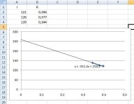
here are the compilation of our max current setting availlable compar eto the shunt value that are set: ( Batt Amp and miliohm)
121 0,396
126 0,377
139 0,344

According to excel spreadsheet the predicted max current the actual shunt preset value has been calculated for is about 260A

I will have to modify a little bit the shunt to make it goes to 140A or more =) but i just worrie that the phase current calculation and protection might also be affected. I'll have to see with Jeka....

Oh.. I just opened the second 14kW max-E i have. The shunt is factory calibrated to 396miliohm and max battery current is 120A :roll:

This one is opened and i had a chance to measure the milivolt directly at the shunt at 100A and i measure 36 milivolt (= 0.36 miliohm.)

But hey guess what! I left the 100.0A continuous from my power supply on the shunt to see if it is stable. And NOT!.. the current reading that was 105A ( about 5% error) slowly raised to 115A !! after a minute! i would say that it was to about 60 celsius.

so.. just like any other controlelr that measure current with a shunt, as the shunt get hot, it lower the REAL current limit witch "help" protect the controller against overheat....

But hey! we like high power!! these shunt have to be cooled with fins!!


EDITED ( new info from Andreym on Youtube):

Although the controller current sensing algorithm has a temperature coefficient compensation, however the T sensor is located not exactly near the shunt, but underneath the aluminium heatsink, so on open stand you will have an error when shunt heats up, however while riding the controller itself will heat up as well and the t° compensation will work as it should.

ShuntR value is limited by firmware, so if you want to make your controller output maximum power, you can add some copper to the shunt to make it value = the lowest value in the settings you can choose, but not lower than that. If actual resistance would be lower than the one set in calibration menu, your current readings on the display and the wattmeter would be inaccurate. However if you make modification to the shunt, this will void the warranty, so instead just flash unlocked firmware version that will also void warranty, but will allow you to set any current you want in profiles without touching the shunt :)


Here is a video of my investigations:

[youtube]q8Q_DJyMw88[/youtube]
 

Attachments

  • Adaptto shunt.jpg
    Adaptto shunt.jpg
    22.1 KB · Views: 4,234
That's a great explanation and video of the Shunt performance and how to determine the resistance value needed! Really helped me understand a little more of the problem I'm having trying to make power with my Max-E and trying to zero my displayed current. Thank You, Dr Bass!
Now that I'm starting to understand, I have a question about my Max-E issue; Can I just measure across the battery ground and charging ground with an ohmmeter to determine the correct value I should enter for "Shunt R" in the "Calibration" menu on my controller? Or would I have to put a load across it like you did in the video, then measure the voltage drop across it to accurately calculate that value in mil-ohms?
Once again, your knowledge is very much appreciated, Dr Bass!

SDog
 
skWarDog said:
That's a great explanation and video of the Shunt performance and how to determine the resistance value needed! Really helped me understand a little more of the problem I'm having trying to make power with my Max-E and trying to zero my displayed current. Thank You, Dr Bass!
Now that I'm starting to understand, I have a question about my Max-E issue; Can I just measure across the battery ground and charging ground with an ohmmeter to determine the correct value I should enter for "Shunt R" in the "Calibration" menu on my controller? Or would I have to put a load across it like you did in the video, then measure the voltage drop across it to accurately calculate that value in mil-ohms?
Once again, your knowledge is very much appreciated, Dr Bass!

SDog

That's exactly: "put a known load across shunt , then measure the voltage drop across it(ON THE PCB where the 2 big NEG big wire solder) to accurately calculate that value in mil-ohms

R=V/I
R(ohm) =Voltage (in Volt) / current (in amp)

Doc
 
thank you for making this very informative video. this helps a lot to understand how the Adaptto controllers work and why everyone has different maximum batt amp settings (and also max phase amps i believe).
On one of my Max-E i only can set 123A batt and 335A phase, while on another i have 138 and 370 or something like this..

DOC, i have a few a specific questions to you about that new 14kW unit (i think i have already barrage you with that questions here but i really would like to know^^):

when i asked adaptto about the differences to 12kW unit, they said it does have better filtering.
during your vid i took a closer look to the caps and they seem to be the same as on 12kW model and i could not spot additional ceramic types.
Is this right?
Or may it be possible that this is not a 14kW controller (since the amps are also limited like on 12kW model)?

about the negative (and postive) bus bar: you mentioned it has about 10GA (or 5,3mm²) cross section.
if you still have your controller open, could you measure the width and thickness of this bus bar?
unfortunately my Max-E are attached to vehicles so i cannot measure it my own..
Beefing up the shunt below a given mOhm value will result in wrong power and SOC readings, so i think it would be helpful to beef up the bus bar and upgrade the wires. larger wires will carry away more heat keeping the shunt cooler. IMO 10GA wires for 14kW (170A cont) controller are MUCH to small.

If i now think about that all, i believe it would be better if you take that Max-E with 8GA wires and that additional ceramic caps for the rear motor, flash it to unlocked and enjoy 170+ batt amps without having worry about blowing it :)
what do you say?
 
Hey doc. Really excited to be seeing you push the limits of what is possible with e-bike hubs once again. I love my mxus 4t, and wanted to know how you made those sweet venting holes.
 
madin88 said:
thank you for making this very informative video. this helps a lot to understand how the Adaptto controllers work and why everyone has different maximum batt amp settings (and also max phase amps i believe).
On one of my Max-E i only can set 123A batt and 335A phase, while on another i have 138 and 370 or something like this..

DOC, i have a few a specific questions to you about that new 14kW unit (i think i have already barrage you with that questions here but i really would like to know^^):

when i asked adaptto about the differences to 12kW unit, they said it does have better filtering.
during your vid i took a closer look to the caps and they seem to be the same as on 12kW model and i could not spot additional ceramic types.
Is this right?
Or may it be possible that this is not a 14kW controller (since the amps are also limited like on 12kW model)?

about the negative (and postive) bus bar: you mentioned it has about 10GA (or 5,3mm²) cross section.
if you still have your controller open, could you measure the width and thickness of this bus bar?
unfortunately my Max-E are attached to vehicles so i cannot measure it my own..
Beefing up the shunt below a given mOhm value will result in wrong power and SOC readings, so i think it would be helpful to beef up the bus bar and upgrade the wires. larger wires will carry away more heat keeping the shunt cooler. IMO 10GA wires for 14kW (170A cont) controller are MUCH to small.

If i now think about that all, i believe it would be better if you take that Max-E with 8GA wires and that additional ceramic caps for the rear motor, flash it to unlocked and enjoy 170+ batt amps without having worry about blowing it :)
what do you say?


Hey Madin, I measured the cross sectional from the copper bus bar of the adapttop MAX E 14kW and it is 1.82mm thick x 4mm width = 7.28mm2
= equivalent to 8.5 AWG

But the shunt section is 1.82mm thick x 2mm width = 4.14mm2 = AWG 11 equivalent

Doc
 
Ebikebert said:
Hey doc. Really excited to be seeing you push the limits of what is possible with e-bike hubs once again. I love my mxus 4t, and wanted to know how you made those sweet venting holes.


The holes on the outer diameter are CNC machined with the help of NYX guys and the round holes on the center are diy with large multidiameter drill bit

Doc
 
thank you master :)
if i calculate with 1,82mm height it would be 7,28mm² for the bar.. maybe a typo somewhere?
 
Back
Top