D's RC Drive Kona DC1

Motor on the downtube? We cant get a mount there? (or is there another downtube:p). It may be possible to do that but with the motor above the swingarm linkage (behind seat) run chain to the gearbox, then on to the crank?
We tried a spoon, and we tried no spoon, didnt really help.

Best solution is probably to put the drive on the front wheel of the Ducati and use it for regen and front wheelspins. *runs off to get the gaffa tape*
 
Yes Miles, can use the BB fixing, and possible the spare shock mounting hole. Both of these are several inches below where the drive needs to be though, we still need a firm fixing on the halfsquare part of the downtube. (under the leters K and O of KONA)
 
Hi Jozzer,

I meant that in the context of D's idea to separate motor and pulley axle.

It's difficult to visualise the clearances from one photo.....

If the large pulley was as high up the seat-tube, as possible, couldn't the motor be on the downtube, nearer to the BB?

Re-use the existing motor mounting plate?
 
Hello to everyone! This has turned into a pretty epic conversion! I want to get this bike riding ASAP! I want to know what the RC motor is capable of! I want to be screaming through some woods like a banshee!! :)

At this point I would like to say that with a 20" wheel we could have the whole system checked for week points and to find out if it works at all in around about 2 weeks (asuming the throttle signal can be sorted for the rc controller)! The last piece of hardware has been designed and as soon as the ali turns up it will be in the hands of our rather capable Machinist to get it finished for us!

I think that even though D wouldn't be particularly happy about having a 20" wheel, it would get this thing off the ground and proven so quickly. Then you could muck about finding a way to keep the 24" wheels and mounting the motor for as long as you like! The point is that it would be working and everyone can see what else needs changing rather than stabbing in the dark! At this point we personally have no idea how the system will perform. I'm not just talking about the motor and controls anymore here. I'm thinking about the whole drivetrain setup. Has it ever been used before? what are the limits? Etc, Etc, etc. test, test, test. can't do that till the motor is mounted! Which if left as is we can do!

We also need to know about weather or not we need to get the controller in good air flow or if it will be ok in the box. I mean look, there are so many unknowns that need to be addressed and I think we are concentrating on the least important right now! I will personally loan a wheel at no cost to get it moving. bearing in mind that to make the motor mount for the seat tube would be a peice of cake and cost f-all, so that if the wheel size is the only issue after that then you have a clear direction to take it in. We've just been looking at how to mount to the down tube and it is going to be a pig! :-(

My worst fear is that it takes another 6 mounths to get the motor mounted to everyones satisfaction to find that everything else sucks and it has been a total waste of time and yet another drive solution needs to be found! Personally I don't think it will come to that, but I would like to know sooner rather than later!

Basically to me it's a no brainer about how to get this moving in the right direction. Fit a smaller wheel EVEN if it's just for one ride, see if everything else works, then at least I know it's not a futile effort to get the 24's fitted. PLUS, it is not invasive to the frame or any of the other components and cost absolutely f**k all!


Ok pic's time!! Yay! :)


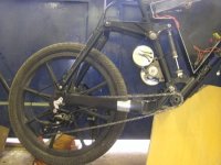
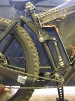
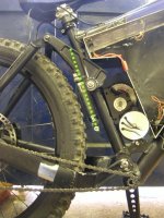
The first two are of the 20" wheel with the motor in the CLOSEST position to where the composite sproket will be mounted. Giving minimal chain langth and keeping everything tight. On full extention there is acrs of room between the motor and tyre; 3", at least the same thicknes as the mototr again. Under full compression, there is still another inch to go leaving plenty of room for a motor cover etc. So that's what I think we should do! Getting it moving!

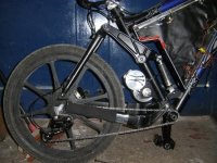
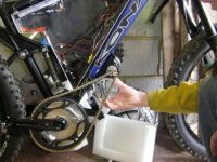
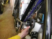
The next lot are with the 24" rear wheel, bearing in mind I would always keep the front wheel 24" for better ground clearance and bump absorbtion bla, bla, bla.

So with the 24's you can just about squeeze in the motor on the lowest possible position, and get a small amount of clearance in the highest position which would be better for chain rap on both sized wheels regardless. But in the highest position, there would be no room for ajusting the chain tension after it starts to stretch! Anyway, with the 24, you would just about be using the standard amount of SAG the sus would normally give you and it would be rubbing the crap out of the motor. Basically there is no where near enough room for the motor to be mounted on the seat tube with 24" wheels, so that is that out the question. Even with modified seat tube! Fully compressed without the motor in the frame there is a maximum of 1.5" gap to put it in!

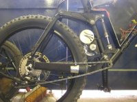
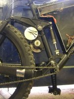
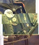
The last two pics are of a possible placement for the motor with the chain and sproket in situe so you can see what's what!

If I've rambled, I'm sorry but I want this bike finished it's been collecting dust long enough!!
 

Attachments

  • 20 with motor.JPG
    20 with motor.JPG
    29.3 KB · Views: 2,839
  • 20 compressed.JPG
    20 compressed.JPG
    36.9 KB · Views: 2,836
  • 24 extended.JPG
    24 extended.JPG
    31.9 KB · Views: 2,836
  • 24 high.JPG
    24 high.JPG
    49.8 KB · Views: 2,844
  • 24 compressed.JPG
    24 compressed.JPG
    53.2 KB · Views: 2,835
  • down tube 1.JPG
    down tube 1.JPG
    36.2 KB · Views: 2,832
  • down tube 2.JPG
    down tube 2.JPG
    32.9 KB · Views: 2,831
You could also consider swapping the shock and the motor. Requires modding the bellcrank and adding linkarms to the shock, but no mods to the basic frame...
 

Attachments

  • DeeC2.jpg
    DeeC2.jpg
    55.1 KB · Views: 2,818
I see where you're coming from!! The problem with that, is that the mount holding the pully and the shaft will still be too thick to fit on the seat tube with the 24" wheels! The pulley mount/holder is 2.5" at the thickest, and there is only 1.5" available to play with. You could mount further down the tube if you wanted, but then you wouldn't be able to fit the go-kart sproket to the cranks and have everything meet.

Again, with the shock being put round the other way with motor on the other side between the seat tube and the box, not enough room. Plus the added problems of re-working all the shock mounts and the like. Too much to be a ble to get right first time. Unless several frames are found so that it could be practiced first!
 
those measurements of available space were in the fully compressed stait so that you know you can still use the full travel of teh bikes suspension!
 
B0B said:
I see where you're coming from!! The problem with that, is that the mount holding the pully and the shaft will still be too thick to fit on the seat tube with the 24" wheels! The pulley mount/holder is 2.5" at the thickest, and there is only 1.5" available to play with. You could mount further down the tube if you wanted, but then you wouldn't be able to fit the go-kart sproket to the cranks and have everything meet.

Yes, looking at the photos again, I can see that..... So, it would mean making 2 new mounts and most of the present gearbox wouldn't be used........

It doesn't look that out of place on the down tube. Bit of a kludge but, how about fabricating a bracket using a circular collar with metal/epoxy infill (moulded in-situ) to conform to the shape of the tube?


As the Irishman said, when asked directions: "I wouldn't start from here..."
 
Gotta love the Irish... :mrgreen:

I see now the downtube location is definitely the spot it wants to be at, so some sort of clamp(s) that integrate into the box somehow, is what is needed.

-- Gary
 
Got to be really carefull when it comes to clamping anything on frames, particularly when the tube isn't a perfect circle.

I have seen in the past where people have over tightened their front mechs on their seat tube and actually crushed the tubing. considering that a front mech can only be tightened so much by a single M5 bolt and can crush the strongest shaped tube on a bike with no other forces being applied to it imagine what 5Kw motor plus clamping on a non-circular tube could do? Basically unless you get the clamp shape perfect you run a huge risk of braking the down tube. Also if anchoring to the battery box, some serious reinforcment would need to be done. Welding is pretty much the only option! You can then reinforce the frame as you go.
 
D,

Let me know if you want a longer bearing tube. It looks like you will have a long shaft to the sprocket. I would rather see the bearing tube extended to take the load than that shaft.

Matt
 
Hi,

recumpence said:
From those pics, it looks like clamps could fit on the downtube just in front of the BB and another clamp just in front of the shock gusset, between that gusset and the battery box.

Matt

Jozzer said:
Mitch, IF i could get a mount on the downtube there would be no problem. I know of noone with the skills needed to make such a complex shape, it would be near impossible to machine even with a CNC (at least it would be very hard to come up with the model in the first place, frame shape would need "mapping".)
So locations Matt suggested are not round or won't work (even with extensions) for some other reason?

GGoodrum said:
I see now the downtube location is definitely the spot it wants to be at, so some sort of clamp(s) that integrate into the box somehow, is what is needed.

-- Gary
I agree, its a good place.

Jozzer said:
With a bracket like this it would be possible to wrap the frame and bolt onto the underside of the battery box both sides, this transfers much of the motors force into the box, which is at the end of the day only 2mm aluminium. It MAY work, or it may tear it all apart and make a big mess. It will be pulling in just the wrong direction to be supported by the tube directly.

But wouldn't it be relatively easy to build mounts that fasten directly to the box, that locate the drive below the down-tube and beef up the box to handle the motor?

One more idea:
http://www.zinncycles.com/mountain-singlespeed.php
Retrofitting Zinn frames later for a fixed chain
All Zinn magnesium frames, both road and hardtail mountain-bike, can work with single-speed or Rohloff rear hubs after a simple, bolt-on dropout substitution.
Build two "bolt-on dropout substitution" plates that move the wheel back two or three inches. The result would be worse handling for tight trails but better high speed handling.


Since the size of the large pulley doesn't seem to be a limiting factor it might be worth considering increasing the large pulley size (Matt groans). Something like 20t/80t for pulleys and 12t/72t for #219 would give about the same reductions. The potential advantages would be:
1. 72 extron might fit as the inner sprocket.
2. Chain sprockets could be closer together and still get good wrap on the small sprocket.
3. The combination of reduced chain speed and using 12t instead of 11t #219 should be a little quieter.

EDIT ADDITION:
B0B said:
Also if anchoring to the battery box, some serious reinforcement would need to be done. Welding is pretty much the only option!

I think the mounting points of the battery box are far enough apart that the individual mount points would not need to be that strong. Think of levers in reverse :)
 
This is ridiculous! It's actually good the the tube is not round, the bracket will not be allowed to rotate. Why can't you get the U brackets like Gary is doing, heat them up and shape them to the square downtube, insert flatbar stock to spread the crushing load, crank em down tight and off you go! Since the battery box is such a tight fit, cut slots in it to allow the U bracket to go into it. No welding, slight battery box cutting, it may not be the prettiest, but Bob is right, it would be nice to know it actually works before all of D's hair falls out.

We all need to vote on the best solution while D is away, it's for his own good and the sanity of Bob and Steve. :twisted:
 
Jozzer said:
Bob's on his way with a pic to show that there is NO way the motor is going on the seattube without a smaller wheel or an extended swingarm.
.

LOL...i think poor ol Deec is the only one that hasn't realized this yet .... blind freddy can see it simply wont fit hehehe i would have
been tearin around on it for the last 2 days with 20s on it if it was mine LoL... be interesting to see how this is finally approached anywayz :)

KiM
 
Hi,

If Matt's suggested solution won't work (the tube looks round in these locations):
recumpence said:
From those pics, it looks like clamps could fit on the down-tube just in front of the BB and another clamp just in front of the shock gusset, between that gusset and the battery box.

Matt

file.php


Jozzer said:
Mitch, IF i could get a mount on the downtube there would be no problem. I know of noone with the skills needed to make such a complex shape, it would be near impossible to machine even with a CNC (at least it would be very hard to come up with the model in the first place, frame shape would need "mapping".)

Would this work? Make clamps with large round holes (big enough to accommodate the down-tube). Wrap the frame in some kind of protective material then mount the clamps on the tube and fill the gaps with some kind of epoxy or carbon fiber which would be bonded to the mount but not the frame? Would epoxy or carbon fiber be strong enough as a filler? If necessary it could be one long clamp which would reduce the necessary strength.

The clamp could be a U-shaped piece on the top and a U-shaped piece on the bottom with gaps on the sides. Something similar might work for Gary's Dahon.


Someone posted on the diyelectriccar forums that a company in Japan gave him a price for a car body of a concept car. He purchased a scale model and they had the technology to somehow scan (not sure if scan is the actual method) the model into a CAD program, scale it up, and then had an automated process for creating molds for the body. If D made mounts using plaster or clay is there an affordable method to CNC the parts from the models?


I cast some simple (not heat treated) aluminum parts in High School Metal Shop. Is casting mounts out of the question financially?
 
Mitch, I think this is a no-go, because the suspension is not all the way compressed in this picture. I think Bob said there is only 1-1/2" of space in this area with the suspension fully compressed using the 24" tire.

-- Gary
 
Hi Gary,

GGoodrum said:
Mitch, I think this is a no-go, because the suspension is not all the way compressed in this picture. I think Bob said there is only 1-1/2" of space in this area with the suspension fully compressed using the 24" tire.

-- Gary

I think the photo I posted was confusing so I changed that. Matt suggested two down-tube clamps, in front of the seat-tube, which would be used to mount the drive and motor under the down-tube.

Wether or not that will work I would like to know if any of the other methods I listed would be a workable way to make a non-round clamp, as I'm sure this won't be the last time the problem comes up.
 
deecanio said:
Cheers Joz,

Whatever happens there are no changes to the battery box

Don't think its an option Luke...?

Dunno if i would be worried about the motor if a log got in their to smash it, be more concerend about my self preservation, anything gets there with enough force to smash the motor your going to be flying through the air at a greater rate of knots than the bike...if you get my drift LoL Stones/rocks will have direct line to the motor/gears though, something getting caught would be likely im sure, either way the motor and niiiice anodized drive unit will take a hammering...


KiM
 
As far as making clamps for that tube. You can do it without anything fancy.

Take cardboard and do the cut and try method until you have a template that fits perfect around the top and bottom edges of the tube. Make one clamp low and one clamp maybe 8" further up the tube.

Now trace the template shape onto a piece of 1/2" aluminum. Then flip it over and trace the shape again so you have both sides. Take a pen and carefully move that line back about an 1/8th inch. Then cut it out on that shifted back line. Now get a sheet of annealed 1/8th aluminum and a lead shot soft blow hammer. Tap a top and bottom piece of aluminum around the tube so they fit nice. This is pretty easy with annealed aluminum.

Drill and tap your top and bottom pieces for a pair of 1/4-20 screws per side on each bracket so they can clamp onto the aluminum wrapped around the tube. Clamp them on, and get everything all tight and snuggled in how it naturally wants to sit. Then cut down as much from the top side of the bracket as you can, so it has a nice flat surface laying close to the tube. Take plate of 1/2" aluminum and lay it along the backs of the brackets, and tack weld this in place. Unbolt the clamps and finish weld it, but be sure to pre-heat and slow cool so you don't warp too badly. Then line up the drive sprockets how you want them, and drill that 1/2" plate in a way that lines up with the mounting holes in Matts bracket. Then bolt that in place.

Now you enjoy being more stealth due to the ability to cover the motor drive easily, you are protected from log/rock damage, you haven't weakend the frame, you didn't need any special CNC tools or processes, it doesn't interfere with suspension, you can run a 24" wheel, and you still have pleanty of room to fit enough LiPo in that battery box to go around the world and back.
 
I think anybody would come to there senses about cutting the battery box. When it comes down to a decision like cutting the battery box, or cutting the frame up? It's a no brainer. You could cut the lower corner of that box out and weld it all back up seamless in 2 hours. The box isn't a structural part of the frame, and it seems pleanty huge to hold all the batteries he would ever need. It's not like that little lower corner was really prime realestate for holding batteries anyways, unless he has some funky triangle battery packs :)
 
Luke --

The part you are missing is that D had a custom 20s3p a123 pack that Steve did for him that is shoe-horned into that custom battery box. Since that is too much voltage for an HV110, Steve reconfigured this pack into a 15s4p configuration. Same number of cells, so hacking up the box is just not an attractive option. Not everyone doing RC-based setups are going to use LiPos. I'm quite happy with a123s, so I'm sticking with them as well. :)

-- Gary
 
I totally missed that part Gary :) Thank you for telling me that. I think A123 is a great battery, and I must have missed reading that he had a custom pack built that fits the contours of the box. That would make it a considderable amount of trouble to change the box and re-configure the pack once again.:(
 
Hi Gary,

Maybe Luke's clamp manufacturing method or something similar would work on the Dahon oval frame.
 
Back
Top