E-powered Inflatable Kayak Intex Explorer.

pullin-gs

1 kW
Joined
Jul 31, 2009
Messages
395
I built this boat in 2018.
I never posted a thread on it dedicated to it.
Anyway, here it is!
It has been a very reliable and utilitarian build since I first christened her in 2018 on Rainbow River in Florida.
I chose an inflatable kayak because of inexpensive price and portability.
That said, the electronics components can be applied to any kayak e-project.
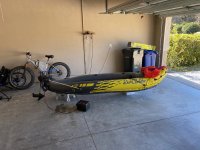
Here is the kayak picture I just took (1/15/2022 ) upon my return from a camping trip in Ocala National Park.
I will post build details later.
In a nutshell:
I used stock Intex Explorer K2 Kayak, 2-Person Inflatable Kayak for bones of project.
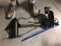
Motor is a Minn-Kota C2 30lb motor. I cut head and resistor-network switch control unit off motor and tossed it.
For speed control, I retrofitted a 60A PWM (!!!) brushed motor speed control which allows for efficient unlimited speed control in forward and reverse).
Battery pack is a 30AH 3S3P pouch lithium ion pack. I get 3 hours or more of electric-only cruise.
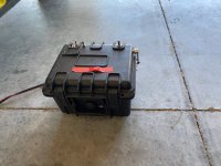
Gun-case box houses pack, controller, electronics.
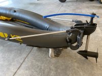
Building mount for motor was tricky. Results were fantastic though. Very reliable. NEVER ONCE HAD AN ISSUE with completed mount. More details later.
663954170.jpg
663955853.jpg
 
Regarding e-powering a kayak....Some (most?) states REQUIRE it to be registered (see my craft# painted on side?) because it has a motor.
This was a pain in the ass because I had to get an MSO from vendor, get it titled in Florida, and pay for craft registration. It cost me $15 and many hours of research and 3 visits to DMV
Check your states laws before you build. Citations are expensive and rangers will get you if your not legally registered.
 
Motor:

I bought a simple Minn Kota C2 (there low end motor 3 speed forward, one speed reverse) 30-lb thrust motor.
The stock speed controller of this motor is simply a multi-position switch which selects speed by switching various large resistors in series with motor and battery.
Very inefficient. Switch out for a reversing PWM speed control and 90% of wattage lost (in heat) experienced by resistor current limiting stock controller is instead used by the motor.
Simply remove control assembly from the motor, several wires lead to motor through downtube. The red/black wires are the DC brushed motor leads, the yellow wires are resistor (which are housed in motor housing) wires. You no longer need resistor wires. Just hook controller up to motor red/black, and hook power up to controller. Done.

You will need a waterproof enclosure for new controller. I put the controller inside the same enclosure I used for the battery and called it a day.
The PWM controller provides gobs more range compared to stock speed controller, especially when you cruise at slower speeds (when resistors would have been reducing current to motor).
Includes forward/reverse features.
Here is a link for the controller I used.
https://www.amazon.com/Controller-DC10-55V-Forward-Brake-Reverse-Adjustable-Potentiometer/dp/B087QDRWBP/ref=sr_1_2?keywords=60a+pwm+speed+...+_sb_noss_2&qid=1642304697&sr=8-2
IMG_0222.JPG
 
Great project and thanks for explaining how you built it.
I bought a 24V 86lbs trolling motor with a broken resistor switch (only top speed works) and a PWM controller last year. Unfortunately haven't been able to build a boat project with it yet.

I think a change in prop will give even more runtime as the props on trolling motors are meant for heavy boats at low speed. Search on YT or the guys changing the prop for a big RC airplane (yes, really) prop.
 
Battery:
I bought 20 surplus SPIM08HP Lithium Polymer cells four years ago.
https://batteryhookup.com/products/2x-spim08hp-3-7v-8ah-cells-with-threaded-insert
9 went to the trolling motor battery for the kayak.
11 went into a 11S1P pack for an e-powered trike (I have over 4500 e-miles on it).
Both packs still going strong.
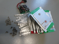
Here is a picture of components that went into the battery box.
I used home-made aluminum clamps to assemble my pack. I created 3 separate "cell-stacks" of three cells in parallel.
I wired the cell-stacks end-to-end (3S) with some 12G wire I had laying around, bolting wires to aluminum clamps.
There used to be a 3S BMS wired up, but I took it off when it failed.
I don't trust them, so I never installed another one (balance has been rock-solid).
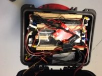
I use a digital voltmeter (see black "activation" button on top-left of box.....digital voltmeter is rectangle right below it sticking out of top. 12.5 is full charge. 11.5 is about 50% used? I keep tabs of capacity using it...very helpful.
The red tape on top holds my 30A fuse. I plug it in when I use motor. Spare is taped to inside of top.
All fittings (terminal screws, thumb screw, motor wire lead clamps, cell clamps, washers, etc.) are stainless.
Control box has pack and speed controller.
Toggle switch (DTSP) is forward/reverse/neutral.
Push button switch is for voltage reading.
Lever on top right of box is my throttle....swing it forward controls speed of motor. Swing all the way back turns it off.
Wire clamps for motor on right side...you can see part of thumb screws.
Wire post on top left are charging terminals.....protected with 5A fuse.
Inside box is main fuse rated at 30A.
Box is water proof....keeps spashes out. But will not protect if whole box gets dunked.

P1050175 (1).gif
IMG_0225 (1).JPG
663954191.jpg
 
Note on operation of motor: Be sure to bench-run it after it has had time to dry. Water will corrode armature&brushes.
When it sits for months of no use, armature&brushes may corrode to point motor will not work.
Here is fix: Mount motor to bench. Connect battery and power up. Wont turn? Carefully flip prop with fingers.
Still wont turn?
Get drill, attach driver with socket that fits prop nut.
DETACH BATTERY.
Attach drill/driver to motor prop nut and run it for a few minutes....reverse drill and run it again for a few minutes.
Now attach battery and see if motor will run by flipping with fingers.
It will probably run, but sputter a bit. Let motor run a few minutes, reverse.....repeat process until motor runs with no sputters both directions.
 
Motor mount....
This was the tricky part. Once dialed-in, I'm happy to report that this solution has been 100% trouble free for years.
Stuff you will need:
Motor mount:
https://www.amazon.com/gp/product/B000NNM4BW/ref=ppx_yo_dt_b_search_asin_title?ie=UTF8&psc=1
Vinyl Glue:
https://www.amazon.com/gp/product/B005LL2XBM/ref=ppx_yo_dt_b_search_asin_title?ie=UTF8&psc=1
Extend support arms:
Buy some aluminum tubes at the hardware store the same diameter, but longer as ones that come with mount kit.
I used these 3ft aluminum tubes (I did not shorten):
https://www.lowes.com/pd/Steelworks-3-4-in-dia-x-3-ft-L-Mill-Finished-Aluminum-Round-Tube/3053653
Mounting points:
These get glued to kayak using vinyl glue. They are support point for motor mount. Buy 4.
https://www.ebay.com/itm/392218302940
 
Nice ! I did a kayak build with Minolta trolling motor on side and heavy lead acid battery. It did Ok
Motor and battery got stolen out of my storage unit though.


Sent from my iPhone using Tapatalk
 
how interesting, longtime lurker but had to register just to respond. this is something i was curious about building, an inflatable kayak + motor i'd be able to bring with me on a plane to remote destinations and fish with.

i didnt think to find motor mounts to glue to the vinyl. originally i was thinking of putting together a lightweight frame to jam inside the inflatable bits, sort of like collapsible tent poles.

another option i was looking at was getting an e-fin for an electric surfboard and 3d printing some type of mounting bracket to the removable fin.

have the motor mounts compromised structure of the vinyl at all?
 
Back
Top