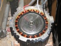
Ecrazyman controller with Kollmorgen?

Well I don't know what to say. I'm not smoking crack-- this is indeed the way it's working for me, and I spent several evenings getting it sorted out. The obvious wiring didn't work; anyone within earshot of the garage could have guessed that :)
 
oops i made an error there in the case where its 60 degrees with the center hall signal flipped, i actually simulated swapping the actual flipped hall sensor with another hall sensor not just swap wires, if you just swap wires then its the same as the rest, the sequence of hall states just reverses. i guess the only explanation for it not working with the right hall wire combination is that the controller cant make sense of the reversed sequence.
 
fitek said:
The obvious wiring didn't work; anyone within earshot of the garage could have guessed that :)

HAHA. I hear that. I did a bit of that myself the other night. I still think I stumbled upon the way too much power combo but hopefully I'll get a chance to try it out on the bike tonight.
 
Ok... I went for a quick test run tonight. The motor didn't seem to have a ton of torque so I'm thinking it might be wired wrong. It did manage 20 mph but then it started cutting in and out. I thought I maybe had a wire getting tugged on since everything is kind of thrown together right now in 'testing' mode. But it seemed to cut out while accelerating. If I backed off the throttle for a couple of seconds and tried again it would work. Does the Kollmorgen have a heat sensor in it?
 
EVTodd said:
...Does the Kollmorgen have a heat sensor in it?

I think the original built-in controller does. With an external controller, it would have no effect.

If the wiring is not right, the peak current could be going high enough to trip the controller. I highly recommend measuring the no-load current at full speed to determine if the wiring is correct.
 
fechter said:
If the wiring is not right, the peak current could be going high enough to trip the controller. I highly recommend measuring the no-load current at full speed to determine if the wiring is correct.

I bet that's the problem. It really doesn't seem quite right anyway. Tons of rpms on the stand and not a whole lot of torque. Time to rewire (and cuss) again.

Where's the best place to get a measurement of the current (don't laugh, I'm still new to a lot of this. lol)?
 
We should have enough info for no cussing. For the Ecrazyman controller, for clockwise direction, I believe it should be blue-green-yellow for both halls and phase wires, both in a clockwise direction looking at the open motor as in the pics. My fingers are crossed for you. If it spins the wrong direction, then just swap the blue and yellow for both.

John
 
EVTodd said:
Where's the best place to get a measurement of the current (don't laugh, I'm still new to a lot of this. lol)?

Between the battery and the controller. The full speed, no load current should be around 2 amps I think.
 
Right, I found some combos that seemed to work on the bench but had little power on the road. Good luck. Honestly, I'm almost surprised the insulation didn't melt off the motor wires. By hour five or six I was letting loose such a torrent of profanity filled vitriol, my girlfriend would give me a concerned look when I came inside for water, and I'm sure the neighbors took the kids inside and shut the doors even though the garage door was down :)
 
I've been using up my profanity usage on my electric motorcycle build. From the machine shop getting my motor mount wrong 3 times, to a company selling me non-standard #41 chain and refusing to refund my money even after I proved to them the chain was incorrect. To top it off, as I'm doing the assembly today I realized that I got too rambunctious with the grinder when I took it apart and inadvertently cut load bearing parts of the frame that I shouldn't have cut. It's been a steady stream of stress relieving language.

In the meantime, back to topic, regarding my nemesis, things electronic, I've just been waiting for you guys to sort it out. I did manage to open one up and reverse the rotation successfully on the first attempt, so I have some degree of confidence that wiring it with the Ecrazy controller will go smoothly. Of course I may be deluding myself, but since I have 3, I will have my sledgehammer handy. I consider my time to be more valuable than one of these motors, so if the frustration builds I will sentence the motor to a swift and sure execution.

Just for the record, my money is still on Blue-Green-Yellow for both hall and phase sequence, in the direction that you want the motor to spin. Let's just hope we all have the same motor and controller wiring or we're in for additional language fresh from the gutter.

John
 
Ok... I finally got around to messing with the motor again. I think my cutting out problem was caused by a bad battery (one I got for free from a friend) and not an overvolt issue.

The wiring I'm testing right now as suggested is: Blue - Green - Yellow going clockwise for both hall and phase wires. Seems to work good. Top speed on the bike is now 21 mph (not too bad for friction drive) with what seems like decent torque. The motor does seem a bit louder but I imagine it will be since it's running at 36 volts now instead of 24. I also still have the motor's lid off so that probably contributes to the noise a bit.
 
EVTodd,

Thanks for the confirmation. Are you using clockwise rotation? ie Motor on the right side of the bike, since you're using a friction drive?

Also, what's the diameter of your friction wheel, so we can get an idea of rpms at 36v?

John
 
fechter said:
So is this how it goes?


Correct, that is how I have it wired at this point. The motor is on your left while sitting on the bike and it's spinning ccw.

One more question... How do you get the fiberglass plate off? I would like to solder the wires directly to the board but I need to get access to the other side. Is it just a matter of cutting into the epoxy (or whatever it is) holding the board on? And once you get it off what are you using to hold it on again?
 
Darn, I was close but no cigar. I forgot to take into consideration that the side in the pic is the backside of the motor, so the clockwise sequence on the wires results in counter clockwise rotation of the shaft. For the record no one needs flogging as both the motors and controllers are wired and color coded in a logical manner. Thanks again, now I don't have to worry about temporary wiring and testing first, and can go straight to doing it right the first time. I just swap the blue and yellow for both, since my motor is on the left but with a chain drive, so I need clockwise rotation.

Oops, almost forgot to ask again. What's the diameter of your friction drive? I have 2 different sprocket sizes and I'd like to get an idea of speed for each.

Also, how's the motor temp? Did you ream out the old controller guts? Mine get's pretty hot to the touch with the factory controller, so if it's not running much cooler, then I'm going to add some big cooling fins. It should be pretty easy as well as effective with that soft aluminum housing. I'll report back and post pics if it works well.

John
 
Sorry about that. I forgot about the roller myself. It has a diameter of 2".

I did indeed pull the old controller guts out. I ended up doing it in my outdoor gas grill like a baked potato. I wrapped it loosely in aluminum foil and baked it for around 50 minutes at 350 degrees. The potting came out pretty easy at that point.

I haven't really used it enough to comment much on the temps. With the drive setup I have, and the way I ride, the stock controller (or motor) never really got that hot in the first place. After the 2 mile test run this morning the ecrazyman (and motor) wasn't very warm at all but I only rode up a small hill and did one flat run to get some idea of the top speed.

Also, since the 3rd battery I was using was bad I used an old sla that I knew was good to test it. I'm not sure if I'll get a tad more speed with a fresh battery.
 
Ouch, that's 3500rpm with likely a sagging batt. With my biggest sprocket that's 33mph on a 26" wheel, which I think would be too much strain on that little motor. 25mph on a 20" might be ok though. On the flipside, a pair of them on my dual motor friction rig might be just the ticket, since it has a 3" roller, and I made it adaptable to any pair of motors. That would put me in the low to mid 30's with my 36v+ ping packs. Then I'd just carry a small 24v pack for the 2nd motor using the factory controller as a helper for takeoffs and hills. First, I'll see how it works with the wheelchair motors, but they make the drive unit so wide that's it's really only going to make sense on a recumbent. I guess I could mount it under a strong DIY bike rack and put blinkers on the ends of the motors to make them look somewhat purposeful. Since I have 3 and the Kollmorgens are well made and compact, a double will be hard to resist if this friction drive works well. I love the idea of no chains or gears, along with 2 motors that work in tandem or separately, so a nearly impossible double failure is required to leave me stranded.

John
 
John in CR said:
Ouch, that's 3500rpm with likely a sagging batt. With my biggest sprocket that's 33mph on a 26" wheel, which I think would be too much strain on that little motor.

Yeah, I'm not sure it would have enough torque to pull that big of a gear. It does work very well with the friction drive but I think a 3" roller would be a bit large too.

Actually, I'm now thinking about getting the 48 volt controller so I can get some more rpms and reduce my roller size for more hill climbing ability.
 
EVTodd said:
One more question... How do you get the fiberglass plate off? I would like to solder the wires directly to the board but I need to get access to the other side. Is it just a matter of cutting into the epoxy (or whatever it is) holding the board on? And once you get it off what are you using to hold it on again?

The plate is held on with epoxy around the edges. Heat the epoxy with a heat gun to around 100C, then use a small flat blade screwdriver or pick to dig away the epoxy (it gets rubbery when hot). Once you dig away enough of it, the plate just lifts out. When replacing it, you could use epoxy or silicone rubber glue.
 
fechter said:
EVTodd said:
One more question... How do you get the fiberglass plate off? I would like to solder the wires directly to the board but I need to get access to the other side. Is it just a matter of cutting into the epoxy (or whatever it is) holding the board on? And once you get it off what are you using to hold it on again?

The plate is held on with epoxy around the edges. Heat the epoxy with a heat gun to around 100C, then use a small flat blade screwdriver or pick to dig away the epoxy (it gets rubbery when hot). Once you dig away enough of it, the plate just lifts out. When replacing it, you could use epoxy or silicone rubber glue.

What's under there? I'd like to just get rid of it. Then I could put heat sink fins on the inside where the original controller was and get air circulation to them for a far more effective way to get the heat out. It might even result in enough space to put some tubing running through that space and eliminate the need for me to add fins on the outside. Is it the heat or rpms that made it fail at 60v?
 
fechter said:
When replacing it, you could use epoxy or silicone rubber glue.

I'd use the high temp silicone used for making gaskets. High temp epoxy is hard to find. If you do use silicone, let it cure for a day or two before closing it up, so the acetic acid released during curing isn't closed up inside your motor.
 
The plate is needed to hold the hall sensors, so you can't get rid of it. You could drill a bunch of big holes in it to allow for air flow.
Kollmorgen apart.jpg
 
That sounds right, the guys who had the magents fly apart were above 48v, so I'd say it can take 5000rpm.
 
Back
Top