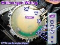
Ecrazyman controller with Kollmorgen?

It flies apart somewhere around 60v. 48v should be safe.

I dont' think it would be too easy to open up the other side of the housing without risking drilling into the windings. If you used an end mill and were very careful about breaking through, possibly.

You might be able to circulate air in and out from the plate side. Heat from the windings is conducted pretty well to the outer housing, so you could just cool the outside.
 
Fechter,

Thanks for the pic. It seems that the hall sensors are mounted directly to that fiberglass plate, so I'm not going to mess with it. With the motor housing being aluminum, I don't think there's much use trying to conduct heat out using air, since the direct conduction into and through the aluminum will be a far better heat pathway. At some point I do want to double or triple the exterior surface area, which as long it has sufficient air flow will increase the heat that it can dissipate by the same amount.

After thinking about it, getting rid of the potting for the factory controller is counterproductive in terms of getting rid of the heat. Epoxy has a many times greater thermal conductivity than air, so increasing the thickness of that air layer by removing the potting is essentially adding insulation. The real heat transfer is taking place where the coils are bonded to the housing anyway, so somehow increasing the area of that connection and/or increasing the surface area between the housing and the outside environment are the best ways to dump heat more effectively.

John
 
Folks used to attach a chunk of sheet alloy to the screw side! It seemes to help the old USPD/HiKol!
otherDoc
 
John in CR said:
After thinking about it, getting rid of the potting for the factory controller is counterproductive in terms of getting rid of the heat. Epoxy has a many times greater thermal conductivity than air, so increasing the thickness of that air layer by removing the potting is essentially adding insulation.

I think the reason for getting rid of the potted controller is to make room for your new wiring. I recall someone stating that if you left it in and added anything extra inside it would push against that fiberglass panel which whould then touch the motor resulting in overheating. I personally think there might be enough room with the old controller in there but you still have a problem with getting the wires out of the casing. The hole to route them out of the motor is also covered in potting material.
 
You don't need to remove all the potting. The one I have has a channel milled out of the former controller to make clearance for the wires, but most of it is still in there.
 
fechter said:
You don't need to remove all the potting. The one I have has a channel milled out of the former controller to make clearance for the wires, but most of it is still in there.

Since you didn't remove all of it where do the wires come out of the motor? The hole for the wires is deep in the potting.
 
It turns out that plate is just a thick plastic. I just scarred around the edge and around the hall sensor portion. Then I just pried it out leaving the hall section in place and intact. This thing cogs so well that I'm seriously considering combining 2 into one motor and use just one controller. The other option is to make the motor even more compact by replacing the 2cm thick end cap with a simple flat plate. Then by using a pair of clutch bearings like I'm doing with the friction drive I can run dual or alternating motors in a compact form, connecting them to the wheel in whatever manner I see fit.

I knew I should have bought more of these motors when I could get them for $35/ea incl shipping. Oh well, I'm sure something even better will be coming down the pipe, and some of the RC motors look promising already. How can we ignore almost 4hp in a 500 gram motor for $56, or 9hp for $150 in less than 2 kilos with an easily manageable rpm/volt? It seems that the hub motor designers are playing catchup.

John
 
EVTodd said:
Since you didn't remove all of it where do the wires come out of the motor? The hole for the wires is deep in the potting.

I don't have a picture of it, but the old controller guts were milled out in a triangular shape around where the wires come in. They milled right through the components, wires, etc.
 
fechter said:
EVTodd said:
Since you didn't remove all of it where do the wires come out of the motor? The hole for the wires is deep in the potting.

I don't have a picture of it, but the old controller guts were milled out in a triangular shape around where the wires come in. They milled right through the components, wires, etc.

That's a good idea. I wish I would have though of it! :D I have a mill that just sat there while I was chipping away at the potting.
 
Folks, just wanted to check in because I hooked up the Ecrazyman to another of my 3 Kolls, and the hall wiring is not weird (BAC rather than ABC). So perhaps that one motor is just oddball.

Additionally, the trace for hall wire A fell off the board. Oops.

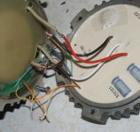
I took a dremel to the glue holding the hall board near the A hall wire. I cut around the thin plastic underneath too, and lifted the board up and soldered a wire to it. That worked.

I am glad I didn't remove the whole board or cut through it, as there is nothing holding it in place except for glue and those hall sensors are just hanging there near the coils. The hall sensors are mounted to the bottom of the board.

Here is the updated image.
 

Attachments

  • koll-innards.jpg
    koll-innards.jpg
    85.2 KB · Views: 2,358
Additional note. The hall wires were damaged 2 more times subsequent to my post. I decided I ought to put a cover plate over the motor. I took the original and tried to use my acetylene torch to remove the epoxy. It kind of works but it smells terrible and takes a long time. So I switched to an angle grinder. This is very messy but works OK until you start popping electrolytic capacitors. These throw off tons of nasty smelling fumes and I had to work with a mask on, the garage door open, and a large fan set on high. After that I used an old chisel which IMO was the best at removing the innards.

The epoxy sticks to the case; but if you drill out the MOSFET mounting screws on the back side (there are six) you could probably wedge a chisel in there and lift the board out.

The cover plate weighs much less with the epoxy removed.

I reused the original wiring sticking out of the cover-- 6 sensor wires and 2 power wires-- and added another power wire. I cut off the connectors at the ends and turned it into the 5 hall wires and 3 power wires. Be careful not to pinch the wires when replacing the cover onto the motor.

The MOSFETs are IRF1305 IIRC.
 
I lit up a propane torch to cook the goop, but a cap popped and almost got me. So I set the lit torch on the case and walked away for half an hour. It was still a pain to chisel out even after that.. should have just gone and bought a piece of scrap ally and drilled a few holes for the screws. You could get creative too and take care of the problem John mentions about thermal mass and conductivity- with some machining of a thick piece of ally. I dont know which would better though, that or a couple holes and a fan.
 
I just opened up the Koll I bought and am wondering about my next steps. Since I have an ecrazyman controller dedicated for the motor, can I just cut off the wires going to the cover plate and wire those directly to the controller? Also, instead of messing with the potting and to reduce weight, can I just screw on a flat piece of aluminum flashing as a temporary cover plate?
 
That or the mill is the smart way to go, I had a mill sitting unused, like the other guy, while I made a mess playing around burning potting. And bursting caps towards my eyes. Pretty dumb. A thin metal cover should protect the internals fine. Maybe some fine stainless mesh would even do. And I would cut the fiberglass while I was in there to aid cooling too.
 
I tried unsuccessfully to reverse my Koll. I put a 5 amp fuse and an amp meter in line with the battery. As soon as I hooked power up to the reversed wiring the fuse blew. I put the wiring back to original, put a new fuse in, and as soon as power was connected the new fuse also blew. Looks like the controller is toast, I guess I will also be doing the external controller mod. I am not sure if I toasted the hall sensors as well.

rewired koll post.jpg

I hooked up a 36V Golden Motor Magic controller I had lying around, and the motor runs great. The GM controller does not need hall sensors to work, I just connected the three phase wires at random and it runs. It was spinning CCW, so I switched two phase wires and now it runs CW. This is defiantly the easy way to run a Kollmorgen in either direction on 36 or 48V. With no hall sensors the motor will not start from a dead stop, but that should not be a problem.
I am afraid to try to connect the hall sensors to the GM controller for fear of toasting it as well. The colors on my wires were different from those posted earlier. I think that I must have swapped the positive (+) hall wire with one of the hall outputs.
 
The sensorless is indeed so much easier than sensored.

But the sensorless controllers that run from a stop generally really stink.

Glad to hear your motor is working for you...
 
hello
I changed direction of my koll by moving the whole hall sensor board by some slots.
just try some different places until you found one that work and have torque.
I really like these motors! I wish they were still at 40$ :wink:
I am running 8s lipo and 60+ amps trough mine with no problems, and it's stock.
at 36v it would run at about 3500 rpm right?
 
well, to revisit this... I just got an ecrazyman controller which he built so that I could run 36 OR 48v (thats at least what I asked him to do, he said sure)
I have strung together every combination you guys have on here and every time the motor will just suddenly jerk on at about 3/4 throttle for a burst and then just slow down and stop. I can keep returning the throttle and the same thing will happen. The only differences I can see between my and the pictures on here is that my red and black wires are in opposite positions in the motor. The hall board is the same. Is it the LVC that would make the motor jerk on and off? I tried both 36 and 48v through the controller with same result.
 
That could do it if your supply sags under load. There is a little LED on the board inside the controller that will blink a code telling you what caused the shutdown. You may need to open one end to see it. I'm not sure I have the code list anymore but somebody will know.
 
fechter said:
That could do it if your supply sags under load. There is a little LED on the board inside the controller that will blink a code telling you what caused the shutdown. You may need to open one end to see it. I'm not sure I have the code list anymore but somebody will know.
YEAH BABY! I was hoping that even though this was so old, that someone would see it and even an original poster at that. cheers to you FECHTER! So if I open the controller and use the throttle, the LED will blink a certain given times or what not or will it blink right away before I even do the throttle. I will try to take a video and post as well.
 
wow. So I tried everything ALL over again, all with the same result. SO frustrating. I had an old scooter throttle hanging around so thought, why not...eureka! The wiring wasnt right but I wasnt getting the shutter or jerking motion.

so for those with a hi kol kollmorgen brushless 24v motor. here was MY order that totally worked. in clockwise fashion. My phase wires went yellow, blue, green from the ecrazyman controller. (black to yellow, white to blue, red to green) if your motor needs to spin CLOCKWISE, switch the blue and green phase wires (at least that is what did it for me to switch rotation). on the hall sensor board it went in the same order, clockwise yellow, blue, green, then the others connected to +,-
This thing flies. but still have to put it on the ground, this was still only a bench test. click on my other link above to the build thread at modifiedelectricscooters.com and you can see more pictures when I put them up.

This thing FLIES at 36v.
 
well.....I spoke too soon. I am so pissed.

So everything was awesome. The wires on the hall sensor were not long enough so instead of splicing them I wanted to resolder. see the pics here...http://forum.modifiedelectricscooters.com/viewtopic.php?f=13&t=1498&p=9947#p9947

I am getting voltage to the controller, but how to can I see if any power is going to the motors when I twist the throttle? before I soldered the hall wires, everything was working. I also took off the phase wires where they were soldered and added longer wire there too. somewhere, no power is getting to the motor. I am so frustrated and depressed....
 
If the controller sees a problem, it will inhibit output. Several things can cause this. The LED on the controller board will blink a code if it sees a problem. I'd suspect the hall wiring first. You can check the Hall power to see if you're getting 5v or so.

Here's the only listing I have for those codes. They seemed to change them with every model, so they may not match your controller. The ones with no description were never figured out but possibly overcurrent and/or overvoltage may be among them. Check your voltage, throttle, and hall signals.

led off: controller running
1 blink led on 0.5s,off 0.5s: stand by
2 blinks led on 0.5s,off 0.5s: throttle fault, or hv brake input
3 blinks led on 0.5s,off 0.5s: locked rotor fault (start speed protection)
4 blinks led on 0.5s,off 0.5s:
5 blinks led on 0.5s,off 0.5s: FET high side short
6 blinks led on 0.5s,off 0.5s: hall sensor fault
7 blinks led on 0.5s,off 0.5s:
8 blinks led on 0.5s,off 0.5s: undervoltage (LVC)
 
Back
Top