
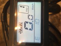
My bike's pedal assist and throttle have been non-operational for a little while now and I can't figure out how to get it working again. It has an error 10 code which I have come to learn is a communication receiving error. I have tried disconnecting the display and discharging the bike. I have checked the wires for a proper connection as well as I can. I have tried switching out the display. I have yet to open up the controller because I don't have the triangular bit to open with. Any help on what I should be doing next to troubleshoot would be greatly appreciated. The error code started while I was going uphill with pedal assist when all the motor's power cut out and the code has remained ever since(the road was dry so no water would have gone in at that time). What is the most likely cause? Will the controller need to be replaced? Would a short in the controller usually be visible? Thank you to all!
You are using an out of date browser. It may not display this or other websites correctly.
You should upgrade or use an alternative browser.
You should upgrade or use an alternative browser.
Error code 10, HELP?
- Thread starter LS7
- Start date
Chalo
100 TW
Inspect and secure all your plugs. This kind of thing is usually either a problem with a plug or a damaged wire. Look for cables that are not fully plugged in, have loose or backed-out terminals in the plug, are significantly corroded, or have physical damage to the insulation.
Most of the controllers I've set up will throw an error if the throttle isn't plugged in, even if PAS operates without throttle input. So I'd start with the throttle plug and cable.
Most of the controllers I've set up will throw an error if the throttle isn't plugged in, even if PAS operates without throttle input. So I'd start with the throttle plug and cable.
This ^^^^^^^^ first.
Normally comm problems are connection problems. However, that's only if the programmers used sensible error code branching in their software, and didnt' just use the "last" or "first" codes as the default for anything they didn't make a specific code for (or just have one code for every error!).
You report that both throttle and PAS are not working; does this mean the entire bike is not working under motor power, or do you have an alternate way of making the motor work that isn't stated?
Complete details on your complete system will help us help you figure out the problem. At minimum, we need to know the
specific brand and model of controller,
specific brand and model of display
Any other details you can provide will help us narrow down what you can look at first. This includes whether the system ever got wet, and how wet, and if there have ever been other problems with the system, times when the bike crashed, fell over, etc. They might seem unrelated but it is very common for a problem created in one incident to only show itself later on when doing something apparently unrelated.
For instance, somewhere around here is a thread where someone had (and knew about but wouldn't tell us) axle wire damage from a crash or the bike falling over, but the only thing they told us about was just an error code on the display that wasnt' about the motor. What it turned out to be after a long drawn out process was the hall sensors on the motor were disconnected from broken wires in the axle wiring. Fixing the wiring fixed the problem.... But if they'd mentioned the wire damage, we'd've recommended fixing that first, and it wouldnt' have taken so long to get them riding again.")
Normally comm problems are connection problems. However, that's only if the programmers used sensible error code branching in their software, and didnt' just use the "last" or "first" codes as the default for anything they didn't make a specific code for (or just have one code for every error!).
You report that both throttle and PAS are not working; does this mean the entire bike is not working under motor power, or do you have an alternate way of making the motor work that isn't stated?
Complete details on your complete system will help us help you figure out the problem. At minimum, we need to know the
specific brand and model of controller,
specific brand and model of display
Any other details you can provide will help us narrow down what you can look at first. This includes whether the system ever got wet, and how wet, and if there have ever been other problems with the system, times when the bike crashed, fell over, etc. They might seem unrelated but it is very common for a problem created in one incident to only show itself later on when doing something apparently unrelated.
For instance, somewhere around here is a thread where someone had (and knew about but wouldn't tell us) axle wire damage from a crash or the bike falling over, but the only thing they told us about was just an error code on the display that wasnt' about the motor. What it turned out to be after a long drawn out process was the hall sensors on the motor were disconnected from broken wires in the axle wiring. Fixing the wiring fixed the problem.... But if they'd mentioned the wire damage, we'd've recommended fixing that first, and it wouldnt' have taken so long to get them riding again.
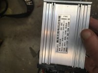
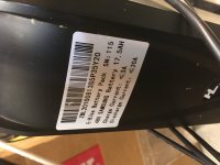
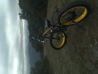
Correct, I cannot use the motor at all. The bike is very new. It’s a 48v 17.5ah 1000W bike. The display is supposedly called HKP-1 but I can’t find much info on it. It’s a smlro controller I have attached some photos.
Attachments
-
 8750F86D-9A3E-4090-8879-9F10DFBE8D7B.jpeg318.1 KB · Views: 485
 -
 2B3B00D2-E265-48BD-8265-988801B8B2F0.jpeg444.5 KB · Views: 485
 -
 4F897CCE-4409-4428-9E4D-00347796A62D.jpeg407.9 KB · Views: 485
 -
 44980DC0-D3CE-41A7-9026-3A236E7C5E11.jpeg242.2 KB · Views: 485
 -
 95AA2811-1F97-48BF-B921-23E6B1FAAF61.jpeg227 KB · Views: 485
 -
 B1EF4E95-9CB7-4C19-A8B7-2EFDFB00F229.jpeg354.3 KB · Views: 485
Chalo said:Inspect and secure all your plugs. This kind of thing is usually either a problem with a plug or a damaged wire. Look for cables that are not fully plugged in, have loose or backed-out terminals in the plug, are significantly corroded, or have physical damage to the insulation.
Most of the controllers I've set up will throw an error if the throttle isn't plugged in, even if PAS operates without throttle input. So I'd start with the throttle plug and cable.
I did already check all the wires/connections but maybe I missed something.
I havent' seen that controller or display before, though I have a controller that looks externally just like it, the labelling is completley different as are the connectors, and its' likely the itnernals are different (and so not the same thing, not useful to compare).
So, if E10 is a comm error, really really a comm error, then it should mean there's a problem talking to or receiving from the dipslay. Since the display has been replaced, then before replacing the controller there is one more test you can try.
There are probalby five pins in the display-controller plug. If so, oen is main battery positive, the other is main battery negative. Another is KSI keyswitch ignition, and the last two are data tx and rx.
A multimeter on 20DCV range, balck lead to bat- whereve ris convenient, can be used to find out which of these pins is which. With display connected and system turned on, probe with red lead on all five pins and write down the pin order/wire color on a drawing fo the conectors, then write the voltage down you see on each one as you chekc them.
When done, turn system off via the display and recheck them on the controller side. Whichever one had battery voltage on it before but doesn't now is t he KSI line. Whichever still has bat voltage is bat+. Whcihever two lines previously had what looked like around 2.5v are the tx/rx lines. The last pin is bat-.
If there are not two lines givieng 2.5v-ish, then that is causing the comm error, mostl likeyl. whichever one its coming from is the one causing the problem.
If you wnat to test witout dispaly to see if it works anywya, power it all off at the battery, then disconnect display, and connect the bat+ wire and the ksi wire on the controller side to turn the contoller on. then turn on battery, and test throttle and pas. if they work, then it means the controller cant talk to the display and get an answer it likes, or the display cant read the controller's signals so it sends a signal to the controller to stay off, and gives an error.
It's still progalby a wire or connector problem causing it, but at least you'll know better which ones to look at.
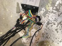
Those are "JST SM" connectors, and a comon problem with them is that pins sometimes don't click into place right hwhen made, so it looks righ t hwhen unplugged, but pins back out when plugged in. gently pushing on the pins from the mating connection end mfight show any like this.
So, if E10 is a comm error, really really a comm error,
then it should mean there's a problem talking to or receiving from the dipslay. Since the display has been replaced, then before replacing the controller there is one more test you can try. There are probalby five pins in the display-controller plug. If so, oen is main battery positive, the other is main battery negative. Another is KSI keyswitch ignition, and the last two are data tx and rx.
A multimeter on 20DCV range, balck lead to bat- whereve ris convenient, can be used to find out which of these pins is which. With display connected and system turned on, probe with red lead on all five pins and write down the pin order/wire color on a drawing fo the conectors, then write the voltage down you see on each one as you chekc them.
When done, turn system off via the display and recheck them on the controller side. Whichever one had battery voltage on it before but doesn't now is t he KSI line. Whichever still has bat voltage is bat+. Whcihever two lines previously had what looked like around 2.5v are the tx/rx lines. The last pin is bat-.
If there are not two lines givieng 2.5v-ish, then that is causing the comm error, mostl likeyl. whichever one its coming from is the one causing the problem.
If you wnat to test witout dispaly to see if it works anywya, power it all off at the battery, then disconnect display, and connect the bat+ wire and the ksi wire on the controller side to turn the contoller on. then turn on battery, and test throttle and pas. if they work, then it means the controller cant talk to the display and get an answer it likes, or the display cant read the controller's signals so it sends a signal to the controller to stay off, and gives an error.
It's still progalby a wire or connector problem causing it, but at least you'll know better which ones to look at.
Those are "JST SM" connectors, and a comon problem with them is that pins sometimes don't click into place right hwhen made, so it looks righ t hwhen unplugged, but pins back out when plugged in. gently pushing on the pins from the mating connection end mfight show any like this.
amberwolf said:I havent' seen that controller or display before, though I have a controller that looks externally just like it, the labelling is completley different as are the connectors, and its' likely the itnernals are different (and so not the same thing, not useful to compare).
So, if E10 is a comm error, really really a comm error,
There are probalby five pins in the display-controller plug. If so, oen is main battery positive, the other is main battery negative. Another is KSI keyswitch ignition, and the last two are data tx and rx.
A multimeter on 20DCV range, balck lead to bat- whereve ris convenient, can be used to find out which of these pins is which. With display connected and system turned on, probe with red lead on all five pins and write down the pin order/wire color on a drawing fo the conectors, then write the voltage down you see on each one as you chekc them.
When done, turn system off via the display and recheck them on the controller side. Whichever one had battery voltage on it before but doesn't now is t he KSI line. Whichever still has bat voltage is bat+. Whcihever two lines previously had what looked like around 2.5v are the tx/rx lines. The last pin is bat-.
If there are not two lines givieng 2.5v-ish, then that is causing the comm error, mostl likeyl. whichever one its coming from is the one causing the problem.
If you wnat to test witout dispaly to see if it works anywya, power it all off at the battery, then disconnect display, and connect the bat+ wire and the ksi wire on the controller side to turn the contoller on. then turn on battery, and test throttle and pas. if they work, then it means the controller cant talk to the display and get an answer it likes, or the display cant read the controller's signals so it sends a signal to the controller to stay off, and gives an error.
It's still progalby a wire or connector problem causing it, but at least you'll know better which ones to look at.
Those are "JST SM" connectors, and a comon problem with them is that pins sometimes don't click into place right hwhen made, so it looks righ t hwhen unplugged, but pins back out when plugged in. gently pushing on the pins from the mating connection end mfight show any like this.
Thank you very much, I will definitely look into this!
amberwolf said:I havent' seen that controller or display before, though I have a controller that looks externally just like it, the labelling is completley different as are the connectors, and its' likely the itnernals are different (and so not the same thing, not useful to compare).
So, if E10 is a comm error, really really a comm error,
There are probalby five pins in the display-controller plug. If so, oen is main battery positive, the other is main battery negative. Another is KSI keyswitch ignition, and the last two are data tx and rx.
A multimeter on 20DCV range, balck lead to bat- whereve ris convenient, can be used to find out which of these pins is which. With display connected and system turned on, probe with red lead on all five pins and write down the pin order/wire color on a drawing fo the conectors, then write the voltage down you see on each one as you chekc them.
When done, turn system off via the display and recheck them on the controller side. Whichever one had battery voltage on it before but doesn't now is t he KSI line. Whichever still has bat voltage is bat+. Whcihever two lines previously had what looked like around 2.5v are the tx/rx lines. The last pin is bat-.
If there are not two lines givieng 2.5v-ish, then that is causing the comm error, mostl likeyl. whichever one its coming from is the one causing the problem.
If you wnat to test witout dispaly to see if it works anywya, power it all off at the battery, then disconnect display, and connect the bat+ wire and the ksi wire on the controller side to turn the contoller on. then turn on battery, and test throttle and pas. if they work, then it means the controller cant talk to the display and get an answer it likes, or the display cant read the controller's signals so it sends a signal to the controller to stay off, and gives an error.
It's still progalby a wire or connector problem causing it, but at least you'll know better which ones to look at.
Those are "JST SM" connectors, and a comon problem with them is that pins sometimes don't click into place right hwhen made, so it looks righ t hwhen unplugged, but pins back out when plugged in. gently pushing on the pins from the mating connection end mfight show any like this.
Hi, thank you for all the info recently. I have decided I want to replace the controller but now I am wondering if I should get a display to go with it and possibly other parts. I am not sure how compatability between all of these things works. Is there anything about a 1000W motor and my battery that could be incompatable with a new setup and possible upgrades. I just want to make sure that I pick a good company or setup so any recommendations would be appreciated.
It is easier to get a kit that includes both controller and display, to be sure they work together. But you have to pick the kit based both on your controller needs, *and* what you want the display to do for you, which can make it a bit harder to find one, as many ads don't tell you anything about the display's capabilities, or which model it is, and there are many similar looking displays that do different sets of things, so you can't assume that because it looks just like some other one that you know does what you want, that the one you're looking at does them too.LS7 said:I have decided I want to replace the controller but now I am wondering if I should get a display to go with it and possibly other parts. I am not sure how compatability between all of these things works.
Some "brands" of displays generally work with a "brand" of controllers...but whether a specific display both works with a specific controller *and* does the other stuff you want depends on both units together. I dont' know of a list that will help pick them.
If they are "generic", then they probably work with anything...but you may have to figure out wiring and replace or rewire connectors to make them connect to your new stuff.Is there anything about a 1000W motor and my battery that could be incompatable with a new setup and possible upgrades.
If the motor is capable of 1000w continous (vs peak) then a controller that does 48v at 20A current limit will work with it, and shouldn't hurt your battery because that's a 48v 17Ah which (assuming it's good quality) means it wont' be being pushed really hard at only 20A max, and would give you almost an hour's runtime if the battery is new. (more runtime if you aren't using full power all the time).
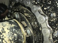
However, the motor looks like a geared hubmotor like some of the Bafang / 8fun hubs. The ones I've had in my hands like that are usually marked for 350w to 750w power levels. If yours is like those, then 1000w continous might be more than it's meant for, and you might want to either make sure you're not always pushing it that hard, or keep monitoring it's temperature, or just get a lesser controller like 48v 10A to 48v 15A, depending on what the motor is meant for (maybe marked on the covers or between the spoke flanges). A lesser controller will give less quick acceleration and will affect hill climbing and offroad capabilities possibly by quite a lot, but it won't push either motor or battery as hard.
Good company depends on what you want.I just want to make sure that I pick a good company or setup so any recommendations would be appreciated.
Do you want a company that makes products that last, or one that warranties and services and supports their stuff, or one that makes cheap stuff, or one that responds quickly? Or some other specific thing(s)?
amberwolf said:It is easier to get a kit that includes both controller and display, to be sure they work together. But you have to pick the kit based both on your controller needs, *and* what you want the display to do for you, which can make it a bit harder to find one, as many ads don't tell you anything about the display's capabilities, or which model it is, and there are many similar looking displays that do different sets of things, so you can't assume that because it looks just like some other one that you know does what you want, that the one you're looking at does them too.LS7 said:I have decided I want to replace the controller but now I am wondering if I should get a display to go with it and possibly other parts. I am not sure how compatability between all of these things works.
Some "brands" of displays generally work with a "brand" of controllers...but whether a specific display both works with a specific controller *and* does the other stuff you want depends on both units together. I dont' know of a list that will help pick them.
If they are "generic", then they probably work with anything...but you may have to figure out wiring and replace or rewire connectors to make them connect to your new stuff.Is there anything about a 1000W motor and my battery that could be incompatable with a new setup and possible upgrades.
If the motor is capable of 1000w continous (vs peak) then a controller that does 48v at 20A current limit will work with it, and shouldn't hurt your battery because that's a 48v 17Ah which (assuming it's good quality) means it wont' be being pushed really hard at only 20A max, and would give you almost an hour's runtime if the battery is new. (more runtime if you aren't using full power all the time).
However, the motor looks like a geared hubmotor like some of the Bafang / 8fun hubs. The ones I've had in my hands like that are usually marked for 350w to 750w power levels. If yours is like those, then 1000w continous might be more than it's meant for, and you might want to either make sure you're not always pushing it that hard, or keep monitoring it's temperature, or just get a lesser controller like 48v 10A to 48v 15A, depending on what the motor is meant for (maybe marked on the covers or between the spoke flanges). A lesser controller will give less quick acceleration and will affect hill climbing and offroad capabilities possibly by quite a lot, but it won't push either motor or battery as hard.
Good company depends on what you want.I just want to make sure that I pick a good company or setup so any recommendations would be appreciated.
Do you want a company that makes products that last, or one that warranties and services and supports their stuff, or one that makes cheap stuff, or one that responds quickly? Or some other specific thing(s)?
I see, that is a lot to consider. As far as what I am looking for in a company is probably just durability and being built to last. Do you have any specific recommendations? I do have a sw900 display.
Similar threads
- Replies
- 3
- Views
- 230
- Replies
- 2
- Views
- 166
- Replies
- 0
- Views
- 193
- Replies
- 6
- Views
- 424
- Replies
- 1
- Views
- 526