You are using an out of date browser. It may not display this or other websites correctly.
You should upgrade or use an alternative browser.
You should upgrade or use an alternative browser.
Field Oriented Control using dsPic33
- Thread starter Burtie
- Start date
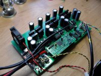
Those boards are quite tidy Burtie. I might be interested in populating one for another go at more power. I have a number of the microchip AN's running on the development board and I may even I have a fair bit of the parts in my inventory (I've got a few of the allegro current sensors at least). Which chip are you using for the gate drive? Do you have a schematic or BOM?
Martin
Martin
bigmoose
1 MW
Great job, and good to see more prototypes appearing! Nothing but good for the development of the next generation controller technology!
Thanks for the comments.
Here are the schematics for the two boards.
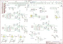
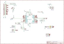 note: processor is actually a dsPIC33FJ128MC204, not the 32MC shown is schematic.
The 128MC has more flash memory and uses DMA to read the analog digital coverters.
The jpg files may not be very clear, so I have also attached some dxf plots
Nothing very new here, mostly tried and tested circuitry.
Slightly experimental part (bottom left of power board) There are three op-amps with cmos switches in the feedback. The amplifiers are connected to the outputs of the phase current sensors.
The processor can configure these amplifiers to have unity gain, or some higher gain (I used x8 ). The Idea is that when measuring small phase currents, the software can automatically select a high gain, to improve the signal to noise ratio from the ADCs. The software compensates for the increased gain by adjusting its internal parameters.
The switched gain hardware works, but I havent written the code to drive it yet. Also the board seems to work ok using just the low gain setting, so it is not essential to populate these two chips.
I use the IRS21864 because it has good drive for two parallel mosfets on each channel, and it uses separate pins for logic ground and power ground.
This enables the ground planes for power and logic to be connected at only a single point, making sure the big currents are kept away from the sensitive circuitry.
The downside is that it is a 14 pin package instead of the usual 8, so takes a bit more space on the board.
Here are the schematics for the two boards.

 note: processor is actually a dsPIC33FJ128MC204, not the 32MC shown is schematic.
 The 128MC has more flash memory and uses DMA to read the analog digital coverters.
The jpg files may not be very clear, so I have also attached some dxf plots
Nothing very new here, mostly tried and tested circuitry.
Slightly experimental part (bottom left of power board) There are three op-amps with cmos switches in the feedback. The amplifiers are connected to the outputs of the phase current sensors.
The processor can configure these amplifiers to have unity gain, or some higher gain (I used x8 ). The Idea is that when measuring small phase currents, the software can automatically select a high gain, to improve the signal to noise ratio from the ADCs. The software compensates for the increased gain by adjusting its internal parameters.
The switched gain hardware works, but I havent written the code to drive it yet. Also the board seems to work ok using just the low gain setting, so it is not essential to populate these two chips.
Yep, all battery and phase voltages and current readings are available to be used by the processor.Arlo1 said:You are running both phase and battery current sensors?
mauimart said:Which chip are you using for the gate drive?
Martin
I use the IRS21864 because it has good drive for two parallel mosfets on each channel, and it uses separate pins for logic ground and power ground.
This enables the ground planes for power and logic to be connected at only a single point, making sure the big currents are kept away from the sensitive circuitry.
The downside is that it is a 14 pin package instead of the usual 8, so takes a bit more space on the board.
Attachments
pendragon8000
100 kW
good on you for keeping it open source code for all. its great to have this attitude on here and gets things developing for the most benifit for all to enjoy.
While being abusive to the controller the other evening, I managed to pop a couple of driver chips. Problem was found to be due to some very bouncy gate signals.
After a bit of tuning with decoupling caps, ground connections, and 'Lebowski style' RC snubbers, the bouce has gone, and we are back in buisness
Video -or it didn't happen.... :|
Ok, here it is running 1kw on the load bench
http://www.youtube.com/watch?v=2Aqke4sdMoM&feature=youtu.be
[youtube]2Aqke4sdMoM[/youtube]
Burtie
whereswally606
100 kW
If I had the spare cash I'd definitely love to play at this too. Do you think you will get a production run this year?
Lebowski
10 MW
any chance of designing a plugin brain board for my controller IC ? It looks like all the hardware on the powerboard is there, like the current
sensors and phase voltage feedback...
sensors and phase voltage feedback...
whereswally606 said:If I had the spare cash I'd definitely love to play at this too. Do you think you will get a production run this year?
No plans to ever market complete controllers, it is just too much work to build an support them to make it economic.
Lebowski said:any chance of designing a plugin brain board for my controller IC ? It looks like all the hardware on the powerboard is there, like the current
sensors and phase voltage feedback...
Yes nice idea, I will try and layout a brain board to take your chip, and see what it would cost to have a few made. That would enable people to make one of these controllers without having to get involved in any programming, or surface-mount soldering.
Any other ideas for PCBs we need, that could be done at the same time ??
Kingfish
100 MW
I recognize from the early notes of this thread that this prototype effort is designed for low induction motors. Can you create (or restate now that you have some experience) a consolidated feature list of what this board does please? Some of us that are keen on your work (me included) would like to know if this controller could be adapted for say… The Dude’s AF motor for example 8)Burtie said:Any other ideas for PCBs we need, that could be done at the same time ??
Thank you kindly from the far side of the pond, KF <nods>
Lebowski
10 MW
If I see correctly from the pictures you have a separate small (red) supply board that derives around 15V from the main battery supply ?
And the 5V is then made from the 15V with a 7805 ?
My controller IC (a 30F4011 at 120 MHz) draws around 200mA from 5V. So the power dissipation in a 7805 that drops 10V is 2W ! That's a lot to dissipate
and will need a heatsink.
Why not build a DCDC converter that derives both the 15V and the 5V from the battery supply using switched mode power supplies (buck converters) ?
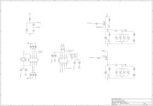
Here is the schematic of the design I use (got 3400km on it already), together with the assembly code for the 12F617. The components used
are what most of us have lying around anyway, except for maybe the PMOS power FET.

Attachments
Kingfish said:I recognize from the early notes of this thread that this prototype effort is designed for low induction motors. Can you create (or restate now that you have some experience) a consolidated feature list of what this board does please? Some of us that are keen on your work (me included) would like to know if this controller could be adapted for say… The Dude’s AF motor for example 8) ...
Well, the software is still in development, so it is probably a bit early to create a full detailed feature list.
Basically it is a controller that runs an FO or vector control algorithm which keeps the stator flux always at 90 degrees to the rotor, resulting is less torque ripple, less noise, (hopefully) improved efficiency, variable regenerative braking, direct phase current monitoring, torque control ...and probably some other stuff I have forgotten.
The algorithm uses Space Vector Modulation (SVM) to control the motor currents.
This is a technique that depends on how far pwm pulses on adjacent phases overlap, rather than directly on how wide the the pwm pulses are.
With symmetrical SVM, windings are energised at the rising edge and again at the falling edge of each PWM pulse.
This effectively doubles the PWM rate for a given switching rate.
Because it is only the ammount of overlap of the pulses that is important, it is possible to energise the winding for very short periods and control this to a very fine degree, (without requiring super fast rise and fall times).
This is all good news for controlling current in low inductance loads.
As for the AF motor, -probably best to hear from 'The Dude' himself
Lebowski said:If I see correctly from the pictures you have a separate small (red) supply board that derives around 15V from the main battery supply ?
And the 5V is then made from the 15V with a 7805 ?
My controller IC (a 30F4011 at 120 MHz) draws around 200mA from 5V. So the power dissipation in a 7805 that drops 10V is 2W ! That's a lot to dissipate
and will need a heatsink.
Why not build a DCDC converter that derives both the 15V and the 5V from the battery supply using switched mode power supplies (buck converters) ?
Yes, agree. I did find the 7805 to get uncomfortably hot when running. I substituted it for a small 5v switching regulator 78ST105, which now runs totally cold.
Your neat dual voltage regulator design is probably a candidate for turning into a discreet pcb module itself.
Burtie
Lebowski
10 MW
hm, I don't use Space Vector Modulation I think (is that where it's jumping between one of 6 possible states ?)
I use 3 independent noise shapers to generate the 3 PWM signals...
My AF motor is actually very easy to drive because it has a relatively high inductance. Now that I have FOC and inductor measurement
on my controller IC, I know v1 has about 400uH in each of the 3 WYE connected coils. I'm expecting about 230uH for v2, the tripple stator motor.
So, no special adaptations are necessary for driving an AF motor...
Kingfish, are you thinking about building a motor yourself ?
Lebowski
10 MW
It needs small RC filters in Ia, Ib, Ic and hall_a, hall_b, hall_c .
the chip doesn't look at the states of the hall signals, it is edge triggered (an edge starts an interrupt routine). So it
needs some RC filters in the hall lines else it will respond to spikes. It only runs sensored at very low rpm so RC filters
are no issue. Maybe it needs some pull up resistor on the hall lines for open-collector output halls ?
I have some (high BW, 20kHz or so) RC filters in Ia, b and c.
You can always leave out the RC and use a wire as bypass...
Further more I would add some more 47uF / 0.1 uF pairs, at least one close to each vdd/vss pair (pins 11/12, 20/21 and 31/32).
I've seen the IC act really funny and unpredictible which was fixed by adding more supply capacitance...
Kingfish
100 MW
>> Fri Feb 08, 2013 12:31 am
I have a modular design in mind that can be used for either front or rear motor. There are some construction issues to resolve though so that maintenance or disassembly is simple. This thread describes my earlier research: I got to a point to where it was time to put my money where my mouth is, however the design also required a custom magnet shape in order to evaluate the best efficiency. The investment in magnet fabrication is much more now than when I began the study two years ago… so I continue to buff and polish the model design & resolving details until I can afford the leap.
The one item I cannot predict well is inductance and how each controller design deals with it. I do believe that Sino phase shape is better than Trap for noise suppression and efficiency. And I am open-minded on new developments, particularly if the sampling rate is above human hearing. The fact is that I suffer from a bit of tinnitus and after a long ride it’s worse, so there is a natural inclination to attenuate the relating issues where possible.
From my earlier experiences with um… let’s just call it high-energy physics… ringing in itself is an expression of energy radiation: We want and desire certain types of radiation for functional applications such as in combustion or energy transfer to say foods. In a controller, ringing – particularly in the audible range seems wasteful. As a result, I am always lurking for alternatives to Chinese-based controller designs for the next investment.
The work that you gentlemen have expressed holds my keen interest, even when I can only comprehend a small amount. My contributions are best with packaging, alloys, thermo, higher-level programming, and UI. And I’m not too bad at gardening either
So forgive me if I perk up every now and then and ask an odd question. Really – I’m a big fan of ye both, and I completely enjoy this particular thread of collaboration. 8)
Cheers, KF
Yes. The short story is that the motor is for my next proposed ride: Motorcycle-class fitting my urban needs in a light cruiser-style targeting around 250cc ICE equivalent in hp and range. (Privately: Something strong enough where I could also take a date on a ride). :wink:Lebowski said:<snip>
My AF motor is actually very easy to drive because it has a relatively high inductance. Now that I have FOC and inductor measurement
on my controller IC, I know v1 has about 400uH in each of the 3 WYE connected coils. I'm expecting about 230uH for v2, the tripple stator motor.
So, no special adaptations are necessary for driving an AF motor...
Kingfish, are you thinking about building a motor yourself ?
I have a modular design in mind that can be used for either front or rear motor. There are some construction issues to resolve though so that maintenance or disassembly is simple. This thread describes my earlier research: I got to a point to where it was time to put my money where my mouth is, however the design also required a custom magnet shape in order to evaluate the best efficiency. The investment in magnet fabrication is much more now than when I began the study two years ago… so I continue to buff and polish the model design & resolving details until I can afford the leap.
The one item I cannot predict well is inductance and how each controller design deals with it. I do believe that Sino phase shape is better than Trap for noise suppression and efficiency. And I am open-minded on new developments, particularly if the sampling rate is above human hearing. The fact is that I suffer from a bit of tinnitus and after a long ride it’s worse, so there is a natural inclination to attenuate the relating issues where possible.
From my earlier experiences with um… let’s just call it high-energy physics… ringing in itself is an expression of energy radiation: We want and desire certain types of radiation for functional applications such as in combustion or energy transfer to say foods. In a controller, ringing – particularly in the audible range seems wasteful. As a result, I am always lurking for alternatives to Chinese-based controller designs for the next investment.
The work that you gentlemen have expressed holds my keen interest, even when I can only comprehend a small amount. My contributions are best with packaging, alloys, thermo, higher-level programming, and UI. And I’m not too bad at gardening either
So forgive me if I perk up every now and then and ask an odd question. Really – I’m a big fan of ye both, and I completely enjoy this particular thread of collaboration. 8)
Cheers, KF
Shenta
10 mW
- Joined
- Jan 19, 2009
- Messages
- 34
Nice work on the programming, I have also try to use the hall sensor to emulate the angle speed, but the hall sensor has obvious misalignments problem, which cause wrong point during commutation. Would you share with us how did you resolve this problem? What I did was just use average timing and made another code to compensate the difference, by assuming one of the 6 commutations was correct position… and as you can see, assuming is not quite correct, so the efficiency suffered pretty much.
I planned to implement a hall sensor callibration routine: spin motor by hand, compare phase voltages and hall transition points,then can calculate and store hall positions.
But currently I just assume the halls have good 120 edeg spacing. Timing was found by altering a phase offset variable at low rpm, to find a position that resulted in the FOC commanding zero Vd (flux vector).
I think the theory is ok, it seems to work ok in practise anyway.
I like your plan for reading the relative hall sensor spacing automatically, I might have to borrow that idea
Combine that with the above technique for setting the hall timing (assuming it is sound), and we have a good way to automatically callibrate the hall positions on-the-fly ??
Edit: Only problem is, you have got to get the motor spinning first, before you can do this :?
kiwifiat
100 W
Thanks to Burtie a quality blank PCB turned up in my mail box today via Royal Mail. I will be building it up over the coming months after the components are to hand and will start a new thread when I commence.
kfong
100 kW
Nice work Burtie, just found this.
Some progress made over the last few weeks,
most of the required features are now working well, including-
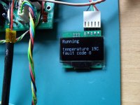
.) Status display shows temperature and most recent fault code information, while the controller is running
.) Parameters can be read and edited using an ascii terminal interface on a computer, or smart phone


View attachment 5
.) Auto hall sensor calibration, just spin the motor by hand and the controller works out the sequence and timing of the sensors, no more trial and error with the sensor and phase wire combinations
.) Temperature of heatsink is monitored by the processor, so we can control a cooling fan and/or shutdown if things get too hot
.) Variable regenerative braking is working well, using an analog hall sensor and a small magnet attached to the hydraulic brake lever. The free play at the lever, before the pads touch the disc, is used to command a variable level of electric braking.

.) Optional switch from sensored to sensorless operation once sufficient speed has been attained.
The sensorless signal is validated against the sensored one, If any loss of sync is detected, the controller reverts to the sensored mode until the senlsorless signal has recovered.
The sensorless signal is preferred (when available) because it has less jitter than the sensored one. Sensor timing jitter can be caused by things like uneven magnet strength and spacing within the motor.
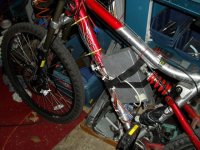
I have made two of these controllers so-far. One is fitted to a test bike with a DD hub motor, running at 4kW peak power, silently,
the familiar DD buzzing noise you hear when using the chinese controllers is completely absent.
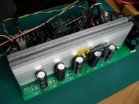
I have not yet attempted to find the power limit of this 12 fet controller, but at present testing levels, I have not seen the heatsink temperature go more than 20 degC above ambient.
Efficiency appears to be about the same as the chinese controller when measured on the dyno, and from looking at the battery consumption after riding a few well tried routes.
The 2nd controller lives on the work bench, and is used for continued development of the firmware.
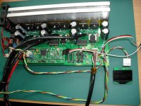
Burtie
most of the required features are now working well, including-
.) Status display shows temperature and most recent fault code information, while the controller is running

.) Parameters can be read and edited using an ascii terminal interface on a computer, or smart phone


View attachment 5
.) Auto hall sensor calibration, just spin the motor by hand and the controller works out the sequence and timing of the sensors, no more trial and error with the sensor and phase wire combinations
.) Temperature of heatsink is monitored by the processor, so we can control a cooling fan and/or shutdown if things get too hot

.) Variable regenerative braking is working well, using an analog hall sensor and a small magnet attached to the hydraulic brake lever. The free play at the lever, before the pads touch the disc, is used to command a variable level of electric braking.

.) Optional switch from sensored to sensorless operation once sufficient speed has been attained.
The sensorless signal is validated against the sensored one, If any loss of sync is detected, the controller reverts to the sensored mode until the senlsorless signal has recovered.
The sensorless signal is preferred (when available) because it has less jitter than the sensored one. Sensor timing jitter can be caused by things like uneven magnet strength and spacing within the motor.
I have made two of these controllers so-far. One is fitted to a test bike with a DD hub motor, running at 4kW peak power, silently,
the familiar DD buzzing noise you hear when using the chinese controllers is completely absent.
I have not yet attempted to find the power limit of this 12 fet controller, but at present testing levels, I have not seen the heatsink temperature go more than 20 degC above ambient.
Efficiency appears to be about the same as the chinese controller when measured on the dyno, and from looking at the battery consumption after riding a few well tried routes.

The 2nd controller lives on the work bench, and is used for continued development of the firmware.

Burtie
pendragon8000
100 kW
great work. what frequency are you using for pwm on the fets? is that how you get it silent?
that little screen is nice to.
the auto phase / hall config is awsome. was that hardvto do? i guess it would be quite logical. does it goto a preset 60,120 deg or does it mesure each one individualy and use the recorded angle eg 118.3 degres?
thanks
PD
that little screen is nice to.
the auto phase / hall config is awsome. was that hardvto do? i guess it would be quite logical. does it goto a preset 60,120 deg or does it mesure each one individualy and use the recorded angle eg 118.3 degres?
thanks
PD
I think the relative silence is because the controller generates sine waves rather than the more traditional trapezoidal waveforms.
The SVPWM and vector update frequency is 20kHz, with this modulation technique the motor is energised both the rising and the falling edge of each pulse, so the rate is equivalent of 40kHz normal pwm.
The auto hall calibration was suprisingly not too hard to do. The calibration determines the individual angle of the start each sector. These precise angles are then used when running the motor.
You use two ADCs to observe two phase voltages so you can determine the direction of rotation. The hall sensor transitions generate interupts.
As the motor rotates, you log the relative times of the zero crossing points and the hall transitions, and the hall codes, for each of the six sectors.
Do this for several (50) electrical revolutions, then calculate an average position for the start of each sector relative to one of the zero crossing points. You can then store the data in flash memory for future use.
Here is the output from the controller console after performing hall calibration, showing-
1) The average angle (in degrees) of the start of each sector
2) The width (in degrees) of each sector
3) The hall code to sector sequence mapping
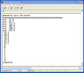
Burtie
The SVPWM and vector update frequency is 20kHz, with this modulation technique the motor is energised both the rising and the falling edge of each pulse, so the rate is equivalent of 40kHz normal pwm.
The auto hall calibration was suprisingly not too hard to do. The calibration determines the individual angle of the start each sector. These precise angles are then used when running the motor.
You use two ADCs to observe two phase voltages so you can determine the direction of rotation. The hall sensor transitions generate interupts.
As the motor rotates, you log the relative times of the zero crossing points and the hall transitions, and the hall codes, for each of the six sectors.
Do this for several (50) electrical revolutions, then calculate an average position for the start of each sector relative to one of the zero crossing points. You can then store the data in flash memory for future use.
Here is the output from the controller console after performing hall calibration, showing-
1) The average angle (in degrees) of the start of each sector
2) The width (in degrees) of each sector
3) The hall code to sector sequence mapping

Burtie
Similar threads
- Replies
- 11
- Views
- 1,826
- Replies
- 16
- Views
- 3,342
- Replies
- 95
- Views
- 17,408


