Field Oriented Control using dsPic33

Nice Burtie!!
Do you have some readings of phase currents compared to supply current under no load? Would be interresting for me to compare them to mine. Iq, Id would be fine too... My FOC algorithm is running now but i underestimated the high phase currents and most likely have to take stronger current sensors.
Many thanks
 
PowerPedro said:
Nice Burtie!!
Do you have some readings of phase currents compared to supply current under no load? Would be interresting for me to compare them to mine. Iq, Id would be fine too... My FOC algorithm is running now but i underestimated the high phase currents and most likely have to take stronger current sensors.
Many thanks


Pedro, Could you start a thread showing all your work with FOC? I am sure many people, including myself, would be interested.

I think the battery/phase current ratio will be proportional to the PWM duty cycle, Which will vary with many factors, including throttle demand. So not sure the test you mention would be very meaningful.
Remember, at low PWM duty, the phase currents may be many many times the battery current.

If your FOC is working ok, in the normal situation, (no field weakening employed) it should keep everything tuned so that your Id is effectively zero.
All the current is used for Iq, to give useful torque.

I guess it would probably be best to chose your phase current sensors to have similar current capability to the output stage you are using?

Burtie
 
OK... I will do that soon.
Currently i am trying to find out why my CPU dies as soon as i start pwm channels?! Very strange problem...
 
Spent the summer riding an ebike powered by one of these controllers, refining the firmware and enjoying the sunshine :D

I wanted the controller to be able to monitor the motor temperature, so it could regulate the max power input when necessary, and I also
had some problems with the existing I2C controller temperature sensor being intermittent in the noisy electrical environment, so vowed to change to analogue temperature sensors TMP35 [3.3v] and LM35 [5v] , (as are standard fitment in some hub motors, esp from EM3EV).

To gain some extra analogue inputs, I want to upgrade from a dsPic33F to a latest generation dsPic33E device (60/70 MIPS).

The 44 pin devices are (almost) pin compatible, so the pcb is the same. But a month down the line I am still struggling with this porting operation.

Edit: It seems the problems I am having are introduced by having to move to the new compiler ( XC16 )
When I use the new compiler with the old processor, I get the same problems.
Seems like some overflow condition is not handled correctly, the symptoms are that the Motor will change direction when running close to full speed. Also the sesorless position detection (observer) will not stabilise.

I think I will put this new processor on the back burner and continue using the original processor with the old compiler ( C30 ) because it works :?

Burtie
 
Nice work Burtie,

I also work on PMSM controller (Both FOC and SSD), therefor I have some tips may save you from controller explosion.

1. Solder with High Temp Solder on all power wires, with Allego sensor, when solder to the board, during high current, the joints will melt and short circuit.
2. Do a temp calibration on the current sensor, Allego sensor are quite good on drifts, but suffer from temperature disturbance.
3. Change to bigger size wires, rule of thumb on electric motorcycle is that 1sqm of wire, no longer than 1meter, can stand 10Amp continues, and 25amps in 30sec.

Can you tell me more about your regen?
 
Hi Shenta, thanks for the tips about the current sensor.

Shenta said:
...Can you tell me more about your regen?

Regenerative braking (with AN1078 FOC) is achieved by just commanding a negative torque value. The bigger the value, the more braking effort you get.
You need to add code to prevent the motor spinning up in reverse after it has stopped. I achieved this by simply preventing the Vq value from becoming negative.

A configurable maximum brake torque limit is added in the controller parameters.
The variable brake torque is requested by an analog hall sensor, stimulated by a magnet attached to the rear brake lever.
The controller has a facility to calibrate the braking input to the output voltage range of the hall sensor.

In practical use,I found it was best to combine the throttle (positive torque request) and brake (negative torque request) was simply to add them together before passing the result to the controller as a net torque request.
This allows the throttle and brake to be used at the same time, which can be useful in some off-road riding situations, the brake lever can be the used to modulate the driving torque, similar to the way you might use the clutch on a gas powered motorbike.
 
Hello,
I'm just about to build a new controller with dsPIC33E (probably) and 6 FETs, and found your design while looking for similars. I like it very much! How is it going nowadays? Did you change to 33E finally or kept 33F?
 
Thanks peters,

I am currently using the controller with a 6 turn MAC on my mountain bike at 3.25kw peak power.

The modest motor is able to survive these power settings because the controller now monitors the motor stator temperature, and progressively reduces the phase current limit, when the temperature exceeds a parameterised threshold.

The ability to control (limit) phase current also prevents excessive torque damaging the sprag clutch on the MAC.


I am still using the 40MIP dsPIC33F on this project, because of the problem I experienced with the new XC16 compiler that is required for the newest 70MIP dsPIC33EP devices.

I suspect the problem has something to do with the way the two different compilers deal with register overflow and saturation conditions.
I have not spent any time trying to fix it, I hoped that Microchip would publish a version of the algorithm that will work with their new compiler soon.

May be they already have, but I have not found it yet ??

Burtie
 
HubLoadBench2.jpg


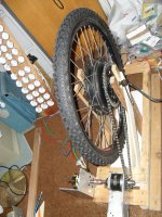
I wanted to be able bench test the controller with a variety of hub motors under load, to enable me to optimise the settings and the filters for a variety of different motors.


The motor driven on its own is almost silent.
Pretty loud now, after adding a chain and a planetary gearbox an a fast spinning Turnigy outrunner (the generator) :eek:

http://youtu.be/VVPsDme0YHU
[youtube]VVPsDme0YHU[/youtube]


Burtie
 
Burtie said:

I wanted to be able bench test the controller with a variety of hub motors under load, to enable me to optimise the settings and the filters for a variety of different motors.
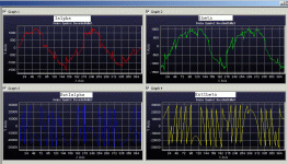
In the video audio it says the bottom left graph is the measured quadrature current and the bottom right is the requested quadrature current and that you should see them following each other pretty closely. I did see them following each other pretty closely but the measured quadrature current was preceding the requested quadrature current. It is hard to pick but I went frame by frame to check. I would have expected the opposite and I'm curious why it didn't match my expectation.
 
Ken Taylor said:
... I'm curious why it didn't match my expectation.

Yes I agree I does look a bit odd.

I think it is due to the way the RTDM graphing tool updates the snapshot for each of the four graphs in turn, starting top left, ending bottom right.
We get to see the data in 'Almost' real time.
 
Burtie said:
I think it is due to the way the RTDM graphing tool updates the snapshot for each of the four graphs in turn, starting top left, ending bottom right.
We get to see the data in 'Almost' real time.
I've no doubt they are "following each other pretty closely" but your explanation indicates the current instrumentation can not show the delay between request and response.

Great project.
 
I think that If you pause the display, the four graphs will show static snapshots that are time aligned with each-other.
 
At 2.11 http://youtu.be/VVPsDme0YHU?t=2m12s request goes to 0 for about 2 secs but response doesn't. Why is that, perhaps a loss of signal?
 
I think this is due to a glitch in the data monitoring mechanism ( RTDM ).

If the observation was real, it would cause upset to the system -which is not evident.
 
Hi,
I am stuck with the same issue using FOC from AN1078 and dsPIC33EP512MC504. (actually I use AN1299 with single current measurement on Ibus and an Allegro sensor, but the controller code is mostly the same). I use XC16 compiler and SK6374 motor.
As Burtie said, there seems to be some overflows in the calculations (see attached graph, the curves on the bottom should be sinus - but they look typical pattern of overflows in calculation, some kind of misplaced most significant bits)
Unfortunately, I cannot use C30 instead, since this dsPIC is not listed in C30, even in the latest v3.31. (maybe there is a trick there to compile for another chip and then use the code for the dsPIC I use - I don't know how)
Playing hard with the user parameters in the code, I could make the motor to start and run, even in closed loop (I had to multiply resistance and inductance values by 10 and decrease the pwm frequency to 8000, among many other tunings). But it does not seem very reliable and stalls at high speed (around 2000rpm) even unloaded. There may also be some hardware issue, as it is my first brushless motor board, but the signals look relatively ok (some ringing during 50-100ns upon commutations though)
I searched microchip forums for AN1078/1299 dsPIC33E and xc16 issue. Found nothing. Does anyone have some other clues in here ?

Anyway, thanks a lot for sharing your project - that is very helpfull for me. I'll post my code and hardware too, if it works...
Pierre
 

Attachments

  • an1299_saturation1.gif
    an1299_saturation1.gif
    88.5 KB · Views: 3,092
Hello Pierre and welcome to ES!
Can this be a compiler optimization problem? I had various issues with gcc optimization on other uC-s (Atmel and TI MSP430), especially when compiled with -o2 and above. So I always use -o0 whenever possible. I did not try dsPIC yet, but XC16 is also a gcc port. Could you try changing this setting?
Concerning C30, as I see it is not supported anymore, Microchip recommends XC16.
 
Hi,
Actually, I keep optimization to -o0 since it will not compile otherwise, it says:
PMSM.c: In function 'FieldWeakening_Inline':
PMSM.c:960:1: error: Argument 0 should be an accumulator register (__builtin_sac)
PMSM.c:960:1: error: Expected DSP accumulator result (__builtin_mpy)
Strange, and I just could find people having similar issue - no solution so far.

Now I will try to compare the asm code produced by xc16 and C30 (using a listed processor). I suspect the error comes during the following code :
Code:
	a_reg = __builtin_mpy(smc1.Gsmopos, smc1.Valpha,0,0,0,0,0,0);
	b_reg = __builtin_mpy(smc1.Gsmopos, smc1.Ealpha,0,0,0,0,0,0);
	a_reg = __builtin_subab(a_reg,b_reg);
	b_reg = __builtin_mpy(smc1.Gsmopos, smc1.Zalpha,0,0,0,0,0,0);
	a_reg = __builtin_subab(a_reg,b_reg);
	b_reg = __builtin_mpy(smc1.Fsmopos, smc1.EstIalpha,0,0,0,0,0,0);
	a_reg = __builtin_addab(a_reg,b_reg);
	smc1.EstIalpha = __builtin_sacr(a_reg,0);
For instance, if smc1.Gsmopos<0x4000 there seem to be less issues than with higher values.
Still much to digg in I presume.
Pierre
 
I checked the code from C30 and XC16 and could not find very significant differences.
As for the optimization issue, I could solve it by changing the local reg definition to volatile. But still, I cannot get high rmp/high amps from my SK6374.
I checked that the DSP time in interrupt is low enough, so there is plenty of margin there, I should be able to PWM at more than 20kHz.
I tend to think the calculations are just assumed for lower amp values as I use, so maybe a downscaling of currents for the computations would help. I will try this when I have time, unfortunately not very soon.
Pierre.
 
pf26 said:
.... But still, I cannot get high rmp/high amps from my SK6374...
Pierre.

Does your sensorless position estimation perhaps fail under these (high rpm/high amps) conditions ?
I guess that, using only a single sensor to resolve the separate phase currents, you will need that sensor to have a suitably high bandwidth.

Burtie
 
Hello,
Yes, it may very well be a position estimation failure. I still could not record what happens upon motor stalling, so I am not sure.

The current sensor does indeed need a high bandwidth, since the current is measured precisely when the phase of interest is powered (MICROCHIP AN1299 explains this very well). There is a parameter called "Critical Minimum window in seconds to measure current through single shunt". The firmware may slightly shift the ON time of a PWM so as to provide this minimum time to make relatively accurate current measurement, and in which case, the next PWM is shifted the opposite way.
Actually, at higher speeds, the PWM duties vary much more than at lower rpms, so it is easier to get enough time to measure current without shifting.

But still, single current measurement time is critical with high PWM frequency, and at high DC input voltages (where ON times are shorter). The Allegro sensor 4us response time (to reach around 90% output) is relatively large, maybe too large for this application.
Hopefully I get some time next week to work on this.
Pierre
 
It took much time, but now it works much better using dsPIC33E and single shunt AN1299. So it was not the chip, nor the AN firmware or compiler..
Main issue was the low bandwith of the ACS758 current sensor. Using a single shunt, current measurement needs be very fast to get differents phase currents depending on the switching state of the FETs. The AN1299 takes care to shift the switching times so as to keep a minimum window for measurement in the middle of a stable FETs state(parameter Tcrit), but ACS758 requires at least 4-5us to reach stable output, which means a minimum tcrit of 9-10us which is too long, especially when using low voltage, low inductance RC motors, and on top of that, I want to use up to 48Vdc (which means still shorter FETs on times).
I tried to shorten the Tcrit and compensate for the first order rising signals (depending on the time elapsed after switching and the last measured value, I could estimate what the correction factor should be to get real current). Better, but still, no real success.
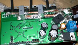
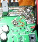
I finally replaced the ACS758 with a shunt and fast OpAmp (MCP6022). The rise time is around 1us and now, it works fine using Tcrit of 2-3us. Now, I need to install the motors on the bicycle to test for real, but I think it will do. (2 SK6374 motors using 52mm diameter polyurethane rollers on both sides of the rim).
Pierre
 

Attachments

  • board_acs758.JPG
    board_acs758.JPG
    288.4 KB · Views: 4,707
  • board_shunt2.JPG
    board_shunt2.JPG
    230.6 KB · Views: 4,707
Dear burtie and all others,
your important thread has been quiet some time, I don't know if you are in it for now.
First I have to thank you and all of the others in here for this awesome thread,
that had cleared up so much for me.

As some of us, I have done a 10kW bldc controller using the familiar AN1017 sinus task, and yes -
after some endless and painstaking cycles I have had a rotating 8kW Motor.

Now the time has come to bring it to the desired 20kW power and yes -
- I should it known better -
but i´m not tired enough to do the next smoking cycles and burn some Euros again, now with FOC.

I just had started the redesign of the board and bring in 2 x ACS758 to do the FOC task, but I´m not familiar enough with this software for now.
A Question:
In your circuit you measure the phase-current with the ACS785´s, but you do it inline not low side. Why do have decided this ?
As I can see the MCLV2 Board uses the Low side scheme witch is due to the cost of course.

Because right now I´m not deep enough inside the phase current measurement of the AN1078:
I expect you have to change the ADC reading in the algorithm right ?
Isn´t the voltage drop different when you measure the phase lines directly vs. do it low-side ?

Just for information, meanwhile I have found a message could be relevant.
Mchp have an Errata along with their new MotorBench Control Application Framework,
and they corrected Slope and Offset for Current Measurements on MCLV2 due to parasitic resistors on this board.
And I have to measure 200A´s !
I have to care for parasitic resistors on the board when doing it in the low side way.

I totally agree to the approach you have done for the startup using hall´s.
I will try to start it with the Hall´s, scale them to the Estimators need´s and then switch over to
Estimator.

thanks for any answer
joerg
 
Back
Top