Field Oriented Control using dsPic33

PowerPedro said:
Am i right that if you write Q15(0.05), that the value 0.05 will be taken and transformed into a fixed point number?!

Yes,
to avoid delays caused by floating point calculations, only integer arithmetic is used in the time critical parts of the application.
All values operated on need to be scaled between .999 and -1 and then converted to a signed 16 bit integer by the macro Q15( )

The actual definition of the macro is:

#define Q15(Float_Value) \
((Float_Value < 0.0) ? (signed int)(32768 * (Float_Value) - 0.5) : (signed int)(32767 * (Float_Value) + 0.5))


see Wikepedia Q(number format):
http://en.wikipedia.org/wiki/Q_(number_format)#Float_to_Q


Alan B said:
You guys are having way too much fun.

I think I'll order the Stellaris TI kit.

Nice work Alan, --I knew you wouldnt resist for long 8)
 
Is it possible to have 100+ kHz PWM frequency and variable phase current limiting (Torque control) with a controller like this?

Happy New Year to all!!!
 
h0tr0d said:
Is it possible to have 100+ kHz PWM frequency and variable phase current limiting (Torque control) with a controller like this?

Happy New Year to all!!!
The new TI stuff claims up to 400khz!
 
Alan B said:
The PWM generator is not the problem, making the high current power switching efficient at those frequencies is.
If you are referring to switching losses, I'd prefer lower phase current spikes and associated losses in controller and motor (with high freq) than lower switching losses and large spikes (with lower PWM freq).

Thanks for the info Arlo1.

What about torque control?
 
It is not a bad idea to raise the switching frequency, but as you go up in power the cost of higher frequency switching rises dramatically.

It is a tangle of engineering tradeoffs with switching losses, hysteresis losses, system costs and other factors.

You'll have to build your own as the cost sensitive ebike markets aren't pushing for higher frequency.
 
Alan B said:
It is not a bad idea to raise the switching frequency, but as you go up in power the cost of higher frequency switching rises dramatically.

It is a tangle of engineering tradeoffs with switching losses, hysteresis losses, system costs and other factors.

You'll have to build your own as the cost sensitive ebike markets aren't pushing for higher frequency.
If I start with a chip capable of high freq, do I have to select special gate drivers and fets because of "only" 100~200khz? If not, cost could be lower because the bus caps could be smaller for example...

Could you expand your thoughts a bit?
 
The power FETs are likely okay, many of them can operate at MHZ though some ratings will suffer.

As you raise the frequency many things change. Significantly more drive power is required to switch the FETs more quickly, and the various components like the energy storage capacitors need to have much lower effective series resistance and inductance (the low ESR feature drives the price up). The PC layout becomes more critical. The design costs more and the components cost more. Going from 16 khz to 128 khz is an increase of 8x in frequency. To switch the same FETs in the same percentage of the cycle it will take 8x the current from the drivers. The current spikes in the driver will be 8 times as large. The charge needed to be delivered to the gates is the same so the drive energy storage capacitance needed is the same. It just needs to be delivered 8 times quicker, like a fire hose instead of a garden hose. There will be extra design challenges due to the higher frequency.

It can be done but costs and effort will go up, and efficiency at some point will go down. How much is it worth? 20-40 khz is more practical than 100-200 khz.

But you can probably build it if you spend enough time and money.
 
Alan B said:
Nice to see someone trying the AVR32, and welcome to ES PowerPedro.

Using the Halls for one rotor position estimate and the motor currents and transforms for another estimate of the rotor position and blending the two with a simple fuzzy logic algorithm seems to be a good approach for this application.


I have thought about fuzzy logic but will not implement it anytime soon.

casainho said:
Is your project OpenSource?

No, it is not open source but i can offer helf for anyone trying to implement FOC with AVR32.

Burtie said:
Yes,
to avoid delays caused by floating point calculations, only integer arithmetic is used in the time critical parts of the application.
All values operated on need to be scaled between .999 and -1 and then converted to a signed 16 bit integer by the macro Q15( )

The actual definition of the macro is:

#define Q15(Float_Value) \
((Float_Value < 0.0) ? (signed int)(32768 * (Float_Value) - 0.5) : (signed int)(32767 * (Float_Value) + 0.5))

I am a bit confused about the amplification factor of 0.05.... Normaly the real value of a PI regulator has to be greater than 1 so i asume that this value corresponds to 0.05 * 64 (for 10Bit ADC) => 3.2!! ?? Am i right or am i getting it wrong?


About the PWM frequency i would recommend a frequency slightly higher than human perception. I configured mine to 20kHz.
 
PowerPedro said:
I am a bit confused about the amplification factor of 0.05.... Normaly the real value of a PI regulator has to be greater than 1 so i asume that this value corresponds to 0.05 * 64 (for 10Bit ADC) => 3.2!! ?? Am i right or am i getting it wrong?

Sorry I am not sure about the exact scaling offhand. But if you need more detail, it is probably best to study the application code for AN1078, which is freely available here:
http://www.microchip.com/stellent/idcplg?IdcService=SS_GET_PAGE&nodeId=1824&appnote=en530042
 
Alan B said:
The power FETs are likely okay, many of them can operate at MHZ though some ratings will suffer.

As you raise the frequency many things change. Significantly more drive power is required to switch the FETs more quickly, and the various components like the energy storage capacitors need to have much lower effective series resistance and inductance (the low ESR feature drives the price up). The PC layout becomes more critical. The design costs more and the components cost more. Going from 16 khz to 128 khz is an increase of 8x in frequency. To switch the same FETs in the same percentage of the cycle it will take 8x the current from the drivers. The current spikes in the driver will be 8 times as large. The charge needed to be delivered to the gates is the same so the drive energy storage capacitance needed is the same. It just needs to be delivered 8 times quicker, like a fire hose instead of a garden hose. There will be extra design challenges due to the higher frequency.

It can be done but costs and effort will go up, and efficiency at some point will go down. How much is it worth? 20-40 khz is more practical than 100-200 khz.

But you can probably build it if you spend enough time and money.

Just remember that while switching losses go up, losses due to current ripple goes down. Therefore you can save money on expencive decoupling, or have efficiency improvement from the reduced current ripple. Since there is a lesser need for bulk capacitance, you can migrate to ceramic capacitors.

I found my efficiency 'sweet spot' around 160kHz. There conduction losses is about 1/2, switching losses about 2/6 and 'stray' losses 1/6. I do have a very tight layout, with glycol-watercooling running through my bikes frame as a radiator :D There isn't much losses at 100A battery at 75V, only about 300W - easily cooled by the bike frame.
 
Teh Stork said:
Just remember that while switching losses go up, losses due to current ripple goes down. Therefore you can save money on expencive decoupling, or have efficiency improvement from the reduced current ripple. Since there is a lesser need for bulk capacitance, you can migrate to ceramic capacitors.

My thoughts exactly. Specially true with a low inductance motor at 0V BEMF.

Teh Stork said:
I found my efficiency 'sweet spot' around 160kHz. There conduction losses is about 1/2, switching losses about 2/6 and 'stray' losses 1/6.

Didn't quite understand your numbers, care to elaborate?
 
h0tr0d said:
Teh Stork said:
I found my efficiency 'sweet spot' around 160kHz. There conduction losses is about 1/2, switching losses about 2/6 and 'stray' losses 1/6.

Didn't quite understand your numbers, care to elaborate?

Conduction losses; R*I^2. On state resistance times phase current squared. Stands for 50% of losses.

Switching losses; 0,5*C*V^2*freq. Fet capacitance times voltage squared halved (energy in capacitor) times freq. I take this value and triple it. This gives a ballpark figure for switching losses - 'Eon' 'Eoff'. This closely matches my measured values. Stands for ~30% of losses.

'Stray losses'. Power supply to gate drivers (10V) inefficiency (the efficient power converted is within switching losses). Current ripple * DF (is quite high actually). Stands for 20% of losses.

To test these parameters I used two weeks to build equipment specifically suited to testing the parameters. Among the things I'm proud of is:
- 3kW purely resistive load (boils water) (used to test conduction losses mostly).
- Inductor bank, low stray capacitance optimized. Made from silicon steel, as you often find in motors. Outfitted with thermocouples to monitor iron losses (Six step generates way more iron losses than FOCSVPWM).
- Current ripple load generator. A load to test how the input capacitors of the inverter react to current ripple.

By combining the purely resistive load and current ripple generator I can keep a constant on time of the fets - this eliminates the switching losses, so I can look at the 'Stray' losses outside switching losses. And I can separate the switching losses better from the other losses.

I understand you want to offer controllers hotrod, but there is more to it than meets the eye. Say you have a complete BOM for the pcb and components that go onto it. Still you must at least double it to account for enclosure, water proofing, cabling and the like. Then comes testing, assembly and packaging. There is a reason why high-end inverters are expencive, they are not mass-produced.

I have a dream to launch my own high-end ebike by the end of my masters studies (2 yrs). I already have batteries, controller and 'cycle analyst' down, I need to optimize the rest of the bike before I can offer it (motor, drivetrain, frame, rims, and the like). The price here in norway will be 5000-7000 dollars, but that is what it will cost if I am to have food on my table. I plan to offer parts kits for DIY'ers on the side, still I won't be competetive with china products. Nor do I want to, making shit that lasts sub 5 years can be continued to be made in china. The 'life cost' of my product will be better anyhow, too bad people only care about upfront costs.

(Extremely off topic on the end there, sorry xD )
 
Teh Stork said:
I have a dream to launch my own high-end ebike by the end of my masters studies (2 yrs). I already have batteries, controller and 'cycle analyst' down, I need to optimize the rest of the bike before I can offer it (motor, drivetrain, frame, rims, and the like). The price here in norway will be 5000-7000 dollars, but that is what it will cost if I am to have food on my table. I plan to offer parts kits for DIY'ers on the side, still I won't be competetive with china products. Nor do I want to, making shit that lasts sub 5 years can be continued to be made in china. The 'life cost' of my product will be better anyhow, too bad people only care about upfront costs.
(Extremely off topic on the end there, sorry xD )
Nice to know your "business plan". Thank you for sharing.
 
I am still having problems with my torq regulation and think that there must be something mixed up :( When i run my application in open loop without any regulation (increasing teta with fixed U_q (regulation output)) as you can see in the code snippet, which is executed every pwm periode synchronized to the adc current sampling...

Code:
	//STEP 1
	if(bldc_q.status & MOTOR_ALLIGN)				//allign rotor to nearest basevector backward
	{

		Teta_degree = AlignDegree;	
		U_q = STARTUP_TORQ;                               //set starup torq
		U_d = 0;                                                    //flux should be zero
		Inverse_Park_Transformation();
		Inverse_Clarke_Transformation_2();
		Calc_SVPWM_TI();
		Generate_PWM_Duties();		
	}
	//STEP 2
	else if(bldc_q.status & MOTOR_OPEN_LOOP)			//spin motor with defined rotation angle speed until Startuphallcnt is reched
	{
		U_q = torq_reference;
		Clarke_Transformation();
		if(Pwm_cnt >= PWM_START_RPM )			//STARTUP_SPEED
		{
			if(mainf_q.status & MOTOR_DIR_CW)		//Clockwise
			{
				Teta_degree++;	
				if(Teta_degree > 360)
					Teta_degree = 1;
			}
			else
			{			
				Teta_degree--;
				if(Teta_degree < 0)
				        Teta_degree = 359;
			}
			Pwm_cnt = 0;
		}					
		Park_Transformation();
		Inverse_Park_Transformation();
		Inverse_Clarke_Transformation_2();
		Calc_SVPWM_TI();
		Generate_PWM_Duties();
	}
	//STEP 3
	else if(bldc_q.status & MOTOR_CLOSED_LOOP)		//calculate FOC with SVPWM
	{
		Clarke_Transformation();
		Calc_angle_New();             //calculate angel based on hallsensors
		Park_Transformation();
		Torq_Regulation_P();
		Flux_Regulation_P();
		Inverse_Park_Transformation();
		Inverse_Clarke_Transformation_2();
		Calc_SVPWM_TI();
		Generate_PWM_Duties();
	}

....I can observe the following:

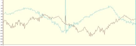
- Measured Ib leads measured Ia sinewave. Therfor also I_beta is leading I_alpha. Is that normal? I think i have seen in some TI documetation that I_alpha should be leading I_beta...
- I_d and I_q (the output of the park transformation) is not constant like i thought it would be under these startup conditions (see attachement)
- I_d and I_q are negative values. Why?? If i later put these values in my regulators with positive reference torq value in closed loop the thing hangs up emediately.

Any comments on this issue would be highly appreciated.
 

Attachments

  • Id_Iq.JPG
    Id_Iq.JPG
    49.5 KB · Views: 1,016
I haven't touched the TI kit, so startup routines are abit new to me. Atmel uses hall-sensors for startup. Are you sure you should 'regulate' the theta angle? In AVR's the 'voltage amplitude' is regulated...
 
I am aware of the following different startup routines using hall sensors in FOC:
- Start with block commutation and switch to FOC after you have enougth hallsensor signals to get interpolated angle values
- Start with FOC in open loop without regulation, fixed torq and flux values and incrementing the comutation angle at a given speed. Switch to torq regulation after you have enougth hallsensor signals to get interpolated angle values.
- AN1078 describes also startup in open loop with the difference that current regulation is on.
- Start with FOC in closed loop and angel resolution of 60° (6 hall sectors) and increment torq reference until motor starts spinning.

I have tried the first 3 but it is not working since there must be some other problem!? Until now i have made my attemts with no load on the motor, so the motor hardly reaches the torq reference. Could this be the problem?
 
Teh Stork said:
I have a dream to launch my own high-end ebike by the end of my masters studies (2 yrs). I already have batteries, controller and 'cycle analyst' down, I need to optimize the rest of the bike before I can offer it (motor, drivetrain, frame, rims, and the like). The price here in norway will be 5000-7000 dollars, but that is what it will cost if I am to have food on my table.
That sounds ambitious. It's hard for one person to do all that and the marketing as well. These guys had an interesting approach http://www.kickstarter.com/projects/faradaybikes/faraday-porteur?ref=live . Get the customers to contribute $177K to fund your product development. They certainly got the marketing right.
Teh Stork said:
(Extremely off topic on the end there, sorry xD )
Interesting though. I often wonder at the motivations of the people who post here.
 
Burtie said:
If you are interested in field oriented control and haven't found it already, you might want to check out the fine work done by Lebowski on this forum, there are a few great threads, documenting his work.
Burtie

Thanks Burtie. I followed that up and observed Lebowski's controller uses Sinusoidal control with extra logic to vary the Sinusoid shape to better match the shape of the measured back EMF. I've mounted an argument there is no advantage in Field Oriented Control over this simpler method for ebikes in the section "Silence Is Beautiful" at http://blog.urremote.com/2013/01/a-stealthy-motor-to-cycle-fast.html .

Is the argument flawed?
 
My custom PCBs arrived about a week ago now, so I have had some time to play with the new hardware.

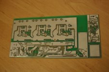
View attachment 3

Solder resist was not applied to the back to allow the traces to be built up.
All components are thru hole, except the processor which is a 44pin tqfp

No solder resist.jpg

The design uses 12 x TO247 format MOSFETS (currently IRFP4468).
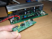
It consists of a Power board, with a small plug in Brain module.

Brain unplugged.jpg

The 28 way brain connector contains all the signals that any full featured FOC design might require, and can use either 3.3v or 5v processors.
The Idea is that the same power board could be used with many different 'Brain' implementations. The particular brain I am using here, is a dsPIC33FJ128MC204 device, with the FOC application ported from microchip AN1078, and modified to use hall position sensing.

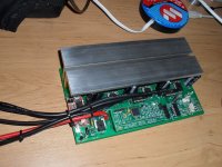
FOController mostly assembled.jpg

So far, I have tested the controller running the basic FOC and have successfully run the dyno with it at about 1kw on 50volts. Hopefully it will be capable of a much higher power rating once I have beefed up the copper tracks!

The plan from here is to gradually develop the extra features:
Variable regenerative braking,
Automatic hall callibration,
Temperature monitoring,
Readouts /Configuration via BT uart (can be on smart phone) or usb cable.
etc ...


Burtie
 
Very nice burtie.
You are running both phase and battery current sensors?
 
Back
Top