
sabbath_can
1 µW
- Joined
- Aug 23, 2022
- Messages
- 1
Hi everyone,
I need your help and opinions about a subject. I have an old ebike with a 24v motor. I wanted to replace its controller and ordered a new one. Today, I received the new controller, but the wires of the new controller look different from the wires of the old one. I could find and connect; phase line wires (green, yellow and blue wires), hall sensor (the socket with 5 wires), power wires (black and blue wires, and throttle wires (black, red and white wires) but I couldn't pair some other wires.
I took the pictures of the wires which I couldn't pair.

- In this photo, there are 4 sockets; the one with black-red-white comes from the throttle and I found that socket on the controller. - The one with green and yellow wires comes from the button on the throttle, but I couldn't find where it goes.
- The one with blue and red wires goes somewhere from the down tube. I don't know where it goes or where to connect to the controller.
- The last socket, behind all others in the photo with 3 wires (blue, red, and yellow) comes from the pedal, but I couldn't find which socket it should be connected to the controller.
The photo of the throttle;

And this is the wire description page of the controller;
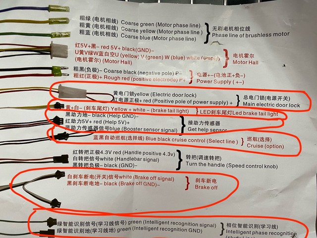
In this photo, I put the wires which I couldn't pair in red lines. I have 3 sockets on the bike side and 6 on the controller needed to be connected.
I hope this explanation is clear enough to get some help.
Thank you...
I need your help and opinions about a subject. I have an old ebike with a 24v motor. I wanted to replace its controller and ordered a new one. Today, I received the new controller, but the wires of the new controller look different from the wires of the old one. I could find and connect; phase line wires (green, yellow and blue wires), hall sensor (the socket with 5 wires), power wires (black and blue wires, and throttle wires (black, red and white wires) but I couldn't pair some other wires.
I took the pictures of the wires which I couldn't pair.
- In this photo, there are 4 sockets; the one with black-red-white comes from the throttle and I found that socket on the controller. - The one with green and yellow wires comes from the button on the throttle, but I couldn't find where it goes.
- The one with blue and red wires goes somewhere from the down tube. I don't know where it goes or where to connect to the controller.
- The last socket, behind all others in the photo with 3 wires (blue, red, and yellow) comes from the pedal, but I couldn't find which socket it should be connected to the controller.
The photo of the throttle;
And this is the wire description page of the controller;
In this photo, I put the wires which I couldn't pair in red lines. I have 3 sockets on the bike side and 6 on the controller needed to be connected.
I hope this explanation is clear enough to get some help.
Thank you...