thundercamel
10 kW
Well...

There are many different ways that the groups can be laid out, but the arrangement as above leaves four cells separated on the right hand side.
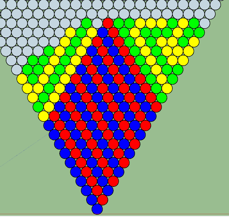
It is possible to work with this, but it will require some copper wire to bridge the four and six cells together to make a 10p group. If you are able to move those four cells to the left hand side, things become easier. An arrangement like this would only require copper to be added to the white strip between the blue and yellow group on the left side, in addition to the positive and negative output terminals of course.
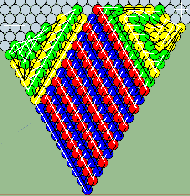
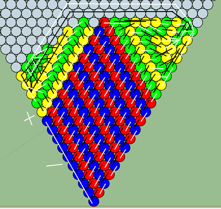
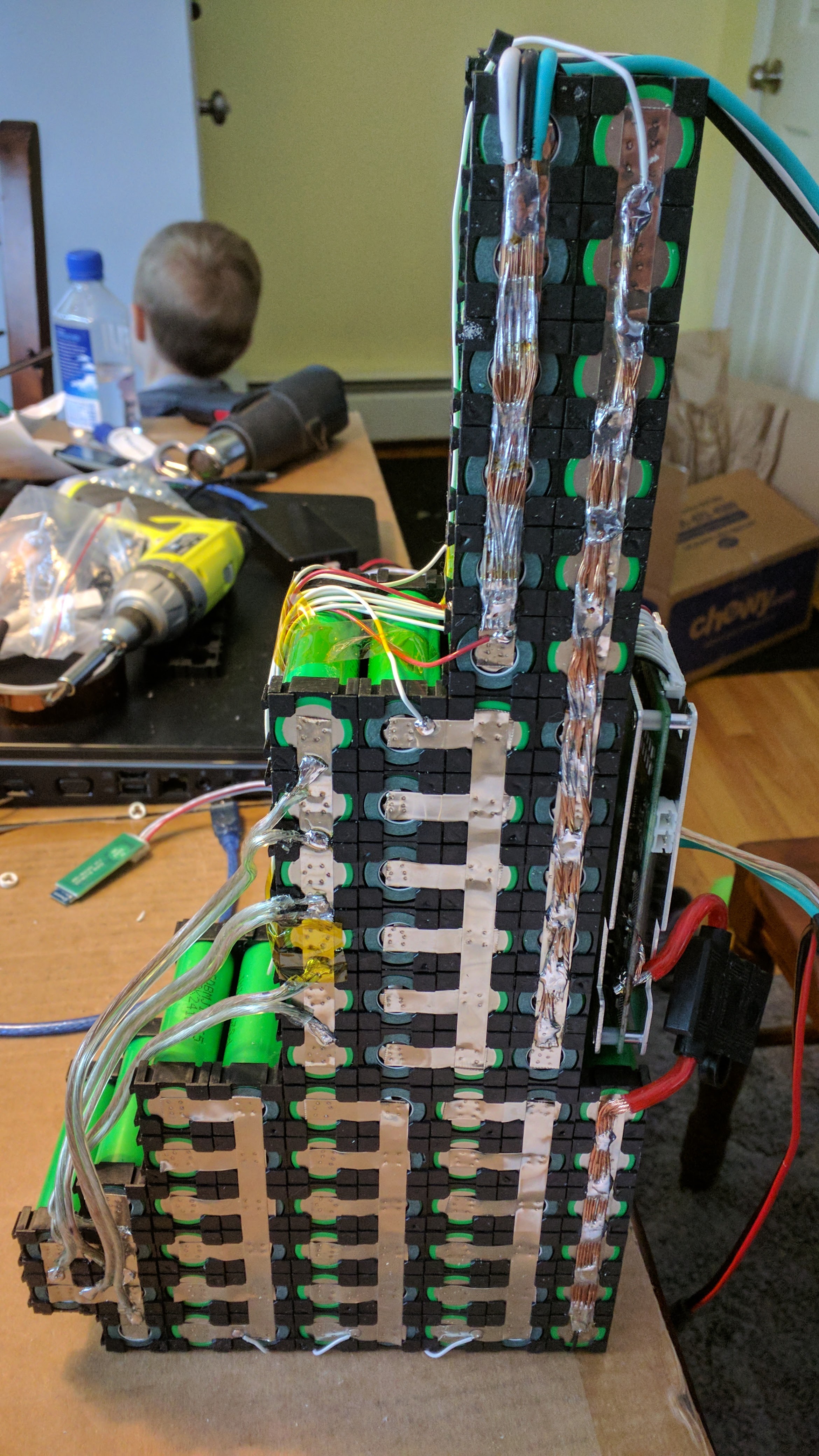
White lines show all the nickel strips needed on the side with the positive and negative output terminals, and black lines show all the nickel strips needed on the other side of the battery. The picture below shows examples on the right hand side shows how I handled the same situation, with positive/negative output terminals and a long copper bridge that would represent your white line between the blue and yellow groups. That copper is only soldered to the nickel strip beneath, and the nickel strip is what's welded to the cells. Solder is placed between the cells to minimize heat getting into the cells. I'm sure other people have different methods as well.
Open as a new tab for full resolution:
There are many different ways that the groups can be laid out, but the arrangement as above leaves four cells separated on the right hand side.
It is possible to work with this, but it will require some copper wire to bridge the four and six cells together to make a 10p group. If you are able to move those four cells to the left hand side, things become easier. An arrangement like this would only require copper to be added to the white strip between the blue and yellow group on the left side, in addition to the positive and negative output terminals of course.
White lines show all the nickel strips needed on the side with the positive and negative output terminals, and black lines show all the nickel strips needed on the other side of the battery. The picture below shows examples on the right hand side shows how I handled the same situation, with positive/negative output terminals and a long copper bridge that would represent your white line between the blue and yellow groups. That copper is only soldered to the nickel strip beneath, and the nickel strip is what's welded to the cells. Solder is placed between the cells to minimize heat getting into the cells. I'm sure other people have different methods as well.
Open as a new tab for full resolution: