From
this thread.
"Controller Wiring...
Note: the controller 5 vdc regulator is not very powerful and is only rated to provide around 100mA or even less.(I've seen down to 40 mA)
Do not short out the supply wires. It will survive a brief short, which I unfortunately can attest too. But probably not for an extended period, which I decline to verify...
Insure correct battery power voltage to controller. Some controllers require an activation (key switch or button...) or "on" signal to it before energizing 5+vdc supply.
Have a map?... Good use it.
If not start by checking the three wires for the 5+vdc regulated output power with a good quality multi-meter.
Mark the positive wire as 5 vdc + (Typically RED and reference color in this thread), Then using a DMM with high resolution and keeping the positive probe there...check the other two wires with the Black test lead, both will provide a grounding path, but the sensor wire has a little resistance in it. So true o vdc battery negative wire or ground will have the highest voltage potential. Mark it 0vdc or ground. (Typically, Black and the reference color in this thread.) With the throttle sensor signal input wire, just a hair less voltage potential. Mark it signal input. (Typically, Green or White, Green as the reference color in this thread.). Example: In my testing, from 5+vdc to true ground meter read 5.07 vdc. And to signal input wire, read 5.06 vdc.
To double check ground. Disconnect battery and allow capacitors to discharge. Then check resistance between negative battery connector connection and previously identified throttle ground, there should be NO resistance what so ever as it is a direct connection."
An alternative, if the controller is not too difficult to open up. Is to check the termination of the wire connection point
labels.
The throttle's signal wire which provides the variable voltage of the throttle to the controller is often labeled with "SP".
Regards,
T.C.
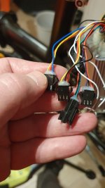
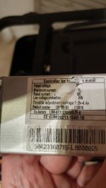
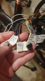
 How do I identify the throttle on this controller. These are the only unused connectors. There are no lights and the bike has a coaster brake (so likely only one brake sensor in use). I can find similar looking controllers online but they all seem slightly different (or do not have a wiring diagram).


