Integrated bottle controller display upgrade

budney

1 µW
Joined
Jun 29, 2020
Messages
3
Looking for advice on how to add a display to this integrated controller.

I just picked up my first e bike last week and it’s great. It’s a little viking evantage, perfect for getting me to work in the city centre. However, it seems to me like quite a dumb e bike. All it has is an on/off switch, and it works with pas so all you can do is pedal to control it. It’s stuck at full power so it’s like playing Mario kart and getting a red mushroom. I’m constantly speeding up on full power then stopping to coast and slow down, it’s not a natural way of cycling.

There was a model of this bike that was advertised as having a 3 mode pas display, so I’m hoping that I can at least add that. If not then I was hoping there was some system like CA or similar that can help me make this e bike a lot smarter.

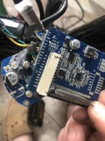
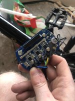
The battery and controller are a bottle integrated system, so the controller sits in the bottom of the battery mount. It’s a neat solution that looks better than the usual alu case with lots of connectors poking out. I opened the controller and unfortunately it was potted, so removing all that was not fun. I also proceeded to pull a filter cap off the board which is a pain...my portable soldering iron didn’t have enough beef so I’ll have to fix that at a later date, I think for now I can manage with half it’s filter capacitance, the battery should be pretty clean.

Looking at the board I can see a lot of connections unused. It only has brakes, a switch, motor and pas sensor connected so I’m hoping one of these others could either be for a display control, or allow me to tap into connections to use cycle analyst. Does anyone have any idea of what they could mean? Also there is a spare header on the board that could be another connection, and there’s solder spaces for what looks like Hall effect connections. So I’m hoping somehow I can upgrade this. If all else fails, perhaps someone knows of a controller that has a pcb similar size to this, that I could stuff into the case. I would hate to have to replace the battery and controller considering it’s all neat and tidy the way it is.

Also I noticed when putting it back together that it actually has a spare 3 pin jst connector. Looking at it it looks like that connector goes to the inputs SE0 and SE1, so could that maybe be the display connector I’m looking for? I tried to get in touch with the manufacturer about what display they used but I’ve had no luck getting a reply.

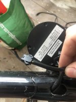
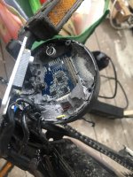
Some photos, anyone have any experience working on this system? The Coyote Energy and the Viking Street Easy used the same ones. Theyre all the same bike just with different branding. I can’t find anything when searching for the controller online. But this spare connector has me hoping.
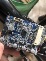
60A38BB2-7D09-4540-93BA-E2C8DD906B97.jpeg
A2DDD8B5-DCFD-4D25-92F1-9A67BA94E202.jpeg
193BB074-1E8C-4046-BA59-516BE39D7B61.jpeg
24BFF372-1DA0-4EEB-A91B-33BB0BBF3B60.jpeg
9E225F02-612A-4ADF-802A-E412AC6BDBBC.jpeg
 
budney said:
There was a model of this bike that was advertised as having a 3 mode pas display, so I’m hoping that I can at least add that.
Almost certainly, you'd have to find one of the specific displays off of one of those versions, for it to be compatible. There's not really any standards for communication protocols or data formats, so displays/controllers are not generally inter-compatible (there are exceptions in that some controllers like ASI have mulitple protocols to switch between, and some controllers/displays have opensource firmware you can flash that let you use different displays, but most won't work that way.)

It's quite possible that the controller is different in those versions, too, so you may have to get both parts to change your bike's behavior.


If not then I was hoping there was some system like CA or similar that can help me make this e bike a lot smarter.
This only works if your controller has a throttle input, because that's how the CA modulates the controller response. (really the only way it can be done and be compatible with everything).

Where does the wire to the pin marked "HAND" go? (potentially could be a throttle input).

Same for "AD1".

Same for "MOD".

If there is no throttle input, then the only easy way to get the CA to be able to modulate controller response is to replace the controller with a generic throttle-only type that doesn't need a display.

If you're going to do that, you could just replace with a new controller/display kit with appropriate power level for the motor, and features you want.

If the motor has no hall sensors you need to use a sensorless controller.

If it would fit inside the battery case, the Baserunner controller from Grin Tech would be a useful way to do this (though it is capable of a lot more than you need it to be, as is the Phaserunner that is a very small hideable controller).


It is quite possible that somewhere in the controller electronics there is a way to modulate the controller's input to a throttle...but it may require reverse-engineering the system and making a schematic to find which pins do what on eac section of the board, particularly around the main MCU chip. Unless you can't replace the controller, this would probably be a last-resort option for most poeple. ;)


I also proceeded to pull a filter cap off the board which is a pain...my portable soldering iron didn’t have enough beef so I’ll have to fix that at a later date, I think for now I can manage with half it’s filter capacitance, the battery should be pretty clean.
They're not there to clean up the input. They're there to buffer the current inside the ocntroller during motor operation, whcih has very large rapid current demand variations. So while it may "work" with less capacitance, it increases the voltage range of the spikes and dips that occur. As long as the spikes don't exceed the ratings of any parts, and the dips don't go below controller LVC, it shouldn't cause any problems, but under heavy loads at the extremes of battery state-of-charge, it could.


It only has brakes, a switch, motor and pas sensor connected
Which specific pins are used for which specific inputs?


Looking at it it looks like that connector goes to the inputs SE0 and SE1, so could that maybe be the display connector I’m looking for?
Most displays that have LCDs or LEDs and buttons them use at least four pins (battery positive (or 5v), serial in, serial out, ground), and those that have a power switch usually have five (includes a return line for the battery positive with the other four).

If there are no buttons and it just displays things, it might use only three, with no serial out line.
 
Did some more digging and have hopefully found some useful info. Called the service department for Viking and got through to a guy who was quite helpful. He said there was no tech documents available as he’s tried himself to get them from the Chinese manufacturer so no luck. Viking bikes he has worked on with displays normally have 2 pin and 3 pin connectors. Also he has no spares lying around as he said the displays he’s come across are the generic ones. So perhaps that 3 pin connector is half of what I need, and I could maybe use the power switch connections.

I traced through all the connections, and it comes out as

Hall pedal sensor cable
Red - 5V
Black - GND
White - FOT

Handlebar cable
Power switch - 24V(labelled as 48 on the board)
Power switch - KEY
Green - GND
Brakes - LB

3 pin jst cable
Black - GND
Green - SE0
Yellow - SE1

So it seems to me, like perhaps I do have the correct connections to use a 5 pin display.

As far as I see it the connections could be
24V
GND
KEY
SE0
SE1

So I would be removing the current power switch that is on there, and replacing with a controller that has the switch, ie an 810. What I’m not so sure on is whether it needs a 4 pin display and only use one data connection. But I think it seems more likely to be a 5 pin. There’s lots of variations of this display but I can’t seem to find any documentation showing the differences.

Re the caps...good to know, hadn’t thought they would be reservoir caps, I’ll make sure to sort that out ASAP. But it’s currently still riding okay.

Hand could perhaps be a throttle input, and the fact that this board says 48 makes me believe it’s been used for bikes other than this one. But I just can’t seem to find anything about it apart from that it was used on the Viking E Vantage/street easy/coyote energy bike.
 
budney said:
Also he has no spares lying around as he said the displays he’s come across are the generic ones.
Which "generic ones"? Displays of different models and brands use different protocols and data formats, as well as which data they can process or send.

So just any old display wont' work; it has to be the right type. Not knowing what that is, odds of one you purchase doing anything more than being able turn it on and off with the 24v and Key wires (and GND) are remote.

If you run across a display that physically looks identical to the ones that come on some of these bikes, you have a better chance, but even then ti could have differnet firmware and protocols.


Hall pedal sensor cable
Red - 5V
Black - GND
White - FOT
That's a good sign that Hand is for a throttle, with FOT perhaps being Foot.


As far as I see it the connections could be
24V
GND
KEY
SE0
SE1
That's likely. You can find out which SE is in vs out by using an oscilloscope, or if necessary a voltmeter on 20vdc. The vm would read around 2.5v for any pin with a digital signal coming out of it, and probably 0v or 5v steady for no signal.


What I’m not so sure on is whether it needs a 4 pin display and only use one data connection. But I think it seems more likely to be a 5 pin. There’s lots of variations of this display but I can’t seem to find any documentation showing the differences.
Anything that lets you use buttons on the display to change *any* settings in the controller requires two serial lines, for any of the common "semistandard" types of display. One into the display out of the controller to show you what the controller sends, and one out of the display into the controller to send changes to the controller.

Some OEM systems use a 1-wire serial system (again, with differnt protocols and data), or CANBUS, but that's uncommon in the "generic" stuff.
 
Okay so some more digging led me to this post

https://endless-sphere.com/forums/viewtopic.php?t=93955

He has a controller built by the same company Santroll, and his comes with a display. His display connections are the same as what I figured, so we’re definitely heading in the right direction. I’m having trouble finding a photo of that specific model of bike he had to see the display, but his description leads me to believe it’s like an 880 or similar.

The generic display the Viking guy mentioned was the 880, the generic ones I mean are the simple ones that all look slightly similar, having a battery meter, on off switch and 3 mode pas switch. As well as some having a cruise control or a light switch. I know there’s lots of variations of the 880 but I’m having trouble finding anywhere that compares them.

I have also emailed Santroll asking if they could share any info, not hoping to get a useful reply however.

I could dig out the scope, but surely I can try connections both ways and hope that one works. I don’t think anything would be damaged if the serial connections were backwards?
 
budney said:
I could dig out the scope, but surely I can try connections both ways and hope that one works. I don’t think anything would be damaged if the serial connections were backwards?
If they used proper output stages for the serial drivers, or typical serial driver chips, it would probably be fine.

If they did one of the common "engineering" cheapouts and skipped drivers and run straight from the MCU lines, then I don't know what would happen--depends on the MCU design itself.

I prefer safe vs sorry, when I don't have spare parts to swap out and throw away the old ones blown up by my mistakes. ;) (since you usually cant' get components to fix anything actually important on these things).
 
If you end up ordering a display, I would recommend getting a kit with controller+display. That way you can still get it up and running if the display for some reason will not work with the controller you have. Considering the quality of most of those cheap controllers, a spare is nice to have anyway.
 
Back
Top