Intermittent no power problem

rick_p

100 W
Joined
Feb 16, 2021
Messages
260
Location
Los Angeles
Hello,

My ebike, which is powered by a BAFANG RMG06 48 volt 750 watt rear hub motor, sometimes works normally and sometimes it doesn't. When it works normally, it's fast, powerful, and quiet. Here are the symptoms when it acts up. With a fully charged battery I turn the bike on and everything lights up like normal, except there is no power to the wheel via throttle or pedal assist. Here is what is strange, if I roll the bike backwards a foot or so and then hit the throttle, it tries to go, you can feel a little pulse from the motor but then it cuts off immediately. If I repeat this process, but instead of using the throttle I just start peddling, it will try to kick in but it makes a growling noise, at which point I pull the brake lever to kill the power to the motor because that is, it can't be good for the motor. The bike doesn't have a throttle only mode by the way, only pedal assist and throttle mode together. If I give up on trying to get the motor working and just simply peddle the bike, it will sometimes kick in at some random amount of time, and from that point run normally. My first thought was it has a bad controller, but when I discovered the rolling backward thing I started questioning that thought and starting thinking it's a motor problem. Has anyone experienced any of these symptoms? All thoughts and suggestions welcome of course.

Thanks, Rick
 
Voltron said:
Well, at least you learned a lot of other good stuff on the way to learning "double check the battery leads first"!🤣🤣
Yes, I learned a lot, I have a much deeper understanding of electric bike systems now, which is incredibly valuable to me.

fechter said:
Good ending. :thumb:
So far so good, I went for a second ride and no return of the problem yet. :)

AngryBob said:
I find myself wondering if this bike charges thru the discharge leads, and if answering the question, posed early on, about if the problem only occurs after a charge, which the OP dismissed as it "couldn't possibly be part of the problem", would have saved a LOT of totally unnecessary, wasted, time, effort, and energy on the part of several people.

Every single thread in this section should have an automatic instruction to check thoroughly for loose wires and connections. This instruction should be detailed, with pictures, repeated at least three times, with a clear and emphatic instruction to perform the procedure AT LEAST twice.

Because they won't freakin do it, and they won't do it right the first time, and a clear majority of the problems are totally and completely due to this failure.

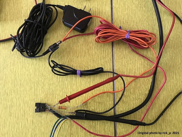
You have every right to be annoyed with me, and I deeply apologize if you or anyone feels that I have wasted their time. With that heart felt apology made, I must disagree with you on one thing though, this thread now contains great information and pictures on how to use a volt meter to make a Hall sensor tester, and other useful information on controllers, and wiring. The photo of the finished tester has been viewed 56 times at the time I wrote this note. If even one person uses that photo to successfully test their motor, I feel that it was well worth my time to make it and post the pictures of it. I can only hope the others feel the same about their contributions to the thread. That doesn’t change the fact that I should have cut the shrink wrap in the very beginning, I was wrong not to do that, but hopefully the others feel that the end result wasn’t a complete waste of their time.

TommyCat said:
May I use your picture in my hall sensor testing thread? Better yet, if you have the time to submit a good picture of your final set-up that I could use. It would be appreciated.
I hope this picture is adequate for use in your other thread. I’m happy to take additional photos if it will benefit the tutorial. Let me know.
 
rick_p said:
I hope this picture is adequate for use in your other thread. I’m happy to take additional photos if it will benefit the tutorial. Let me know.


Very kind of you to offer! As your most recent ones had the small resistor and hall harness a bit harder to see. I decided to go with this pic as of now, with the resistor changed to a 10K. :)


OjKkEQw.jpg


At it's new home here...
https://electricbike.com/forum/foru...-motor-s-phase-wiring-hall-sensors-and-wiring

Only thing I would change is the uninsulated wires that could possibly short, but it more fully gets the diagram across I think.


All's well that ends well! It's been a pleasure working with you.


Best regards,
T.C.
 
TommyCat said:
Very kind of you to offer! As your most recent ones had the small resistor and hall harness a bit harder to see. I decided to go with this pic as of now, with the resistor changed to a 10K. :)

At it's new home here...
https://electricbike.com/forum/foru...-motor-s-phase-wiring-hall-sensors-and-wiring

Only thing I would change is the uninsulated wires that could possibly short, but it more fully gets the diagram across I think.
Very nice of you to add the photo credit ;) thanks.
 
You did not answer the question.

Does you bike charge thru the discharge leads or do you use a separate charging port?
 
AngryBob said:
You did not answer the question.

Does you bike charge thru the discharge leads or do you use a separate charging port?
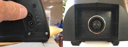
Sorry for the lack of response to your question, I wasn't quite sure what a discharge port is, but I believe your more recent question clarifies that you're asking if the same port is used to both charge the battery and power the bike. They are separate ports.
battery-ports.jpg
 
As much as I'd hoped the repaired wire had solved the problem, alas it has not, it returned this morning. It returned in much the usual way, when I first turned it on and took off, the nasty growling sound reared it's ugly head. I braked a couple of times to kill the power to the motor and then as usual, lights are on but no power until I ride for a while when it will eventually kick in on it's own. Today I noticed something slightly different, instead of it being fine for the rest of my ride once it kicks in, it starting growling when the motor was working, so I braked to kill the power and then had to peddle all the way home. It looks like I'll be testing those Hall sensors after all.
 
I don't want to be the one to say ha!... but ha!
I was having trouble figuring out how a loose battery wire could act just like a bad Hall response but didn't want to rain on the repair parade.🤣🤣

Just btw, a battery could have separate exterior ports for charge/discharge, but still be wired together inside before the BMS, as opposed to going to different parts of the BMS. I'm not sure if there's a way to tell electrically from the outside, as opposed to visual inspection.
 
Voltron said:
I don't want to be the one to say ha!... but ha!
I was having trouble figuring out how a loose battery wire could act just like a bad Hall response but didn't want to rain on the repair parade.🤣🤣
I wanted to think positive, but in the back of my mind I was doubtful it was the wire as well because even though it was loose enough for a slight tug to pull it out of the connector, it was definitely in there, and it had shrink wrap around it to hold it there, so it was probably making a connection.

I tested the Hall sensors and thankfully they all checked out perfectly, all three sensors alternated precisely between 5 volts and .01 volts as I slowly rotated the wheel backwards. The homemade tester worked like a dream :thumb: :)

Since I was all set up I decided to test the Hall sensors using the battery instead of the AC adapter as well, so I connected the controller and used the thin wire probes for the meter. This is when things got really interesting, when I did the first test the motor was working via throttle and PAS, and each of the sensors alternated precisely between 3 volts and .01 volts. Then I messed with the bike (turned it on and off, rolled it backwards, etc) until the no power problem occurred, and then tested again, and this time the yellow and green sensor wires alternated precisely between 3 volts and .01 volts, but the blue sensor wire barely moved, it alternated between maybe .09 volts and .01 volts at most.

I'd love to get your opinion on this, but it sure seems like a bad controller to me.
 
The hall sensor signal line is pulled up by a resistor in the controller and the sensor pulls it down. If that resistor was bad, the signal would stay low. If the hall sensor wiring was shorted to ground somewhere, you'd also see the signal stay low.

One test would be to place a 10k or so resistor between the suspect signal wire and the 5v supply line feeding the halls. This resistor would duplicate the one in the controller. If you still get no signal voltage when it acts up, you have a short in the signal line somewhere. If it fixes the problem, make the resistor permanent. A short could happen anywhere between the sensor and the controller board. Usually wiggling the wires will cause a change in behavior when you have an intermittent short. If you get in the "fail mode" and watch the signal voltage when it's supposed to be high and start wiggling wires, you may be able to narrow down where the problem is.
 
rick_p said:
Since I was all set up I decided to test the Hall sensors using the battery instead of the AC adapter as well, so I connected the controller and used the thin wire probes for the meter. This is when things got really interesting, when I did the first test the motor was working via throttle and PAS, and each of the sensors alternated precisely between 3 volts and .01 volts. Then I messed with the bike (turned it on and off, rolled it backwards, etc) until the no power problem occurred, and then tested again, and this time the yellow and green sensor wires alternated precisely between 3 volts and .01 volts, but the blue sensor wire barely moved, it alternated between maybe .09 volts and .01 volts at most.

I'd love to get your opinion on this, but it sure seems like a bad controller to me.
This indicates a connection problem with one of these two things:
--between the controller's 5v thru the pullup resistor to the blue signal wire.
--between the signal-wire side of the pullup resistor to the controller's input pad for the blue wire.
--between the controller's input pad for the blue wire and the point it connects to the motor's hall connector.

The last is almost always where that problem would be, and almost always it is at the connector end.
The first is very unlikely to be intermittent, but could be a cold solder joint on the resistor.
The middle is possible but would usually be temperature related, where when warmer it always works and when colder it intermittenly or completely doesn't, from a broken trace on a PCB or broken via between layers.
 
amberwolf said:
This indicates a connection problem with one of these two things:
--between the controller's 5v thru the pullup resistor to the blue signal wire.
--between the signal-wire side of the pullup resistor to the controller's input pad for the blue wire.
--between the controller's input pad for the blue wire and the point it connects to the motor's hall connector.

The last is almost always where that problem would be, and almost always it is at the connector end.
The first is very unlikely to be intermittent, but could be a cold solder joint on the resistor.
The middle is possible but would usually be temperature related, where when warmer it always works and when colder it intermittenly or completely doesn't, from a broken trace on a PCB or broken via between layers.
Due to my lack of knowledge of these things, I'm not sure where to look at this point, I don't know where these things are, which also means I'm not sure if I would able to test any of these connections. They mostly sound like they are inside the controller housing, or maybe at the Hall connector on the outside of the controller's housing, but unless I'm not understanding my options at this point, and given that the controller's electronics are completely inaccessible, it only leaves me checking the wires and their continuity through the Hall connector on the controller's pigtail, which I have already done.

Therefore, if I am correct on my assessment of what you're saying, my best bet is to simply replace the controller. Is that correct?
 
With how cheap they are these days, yes. Then you'll be riding reliably while you tinker with the other one.
To me, the rolling it backwards trigger, and messing with it to get the error, and the perfect running the rest of the time suggests still a bad connection in a wire somewhere. But they can be so hard to track down when intermittent, sometimes a wire will be mostly broken from flexing, but hidden under the insulation that is still fine, but every time you probe it, flexes enough to have continuity again, i.e. Schrodingers wire 🤣
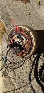
Maybe somewhere like here, where the red power wire for the Hall sensors splits out into three, for example.
IMG_20210218_091344977~2.jpg
Or right where they all exit out of the axle into the motor.. in this pic again, to the lower right you can see rub marks on the insulation of the phase wire near the wire exit from rubbing inside the case. So maybe something like that is happening, but with a sensor wire, where the backwards roll moves it just enough. Maybe the growling is you listening closer, but could also be the prob getting worse slowly, and growling more as the connection slowly flexes more.

At least if you get a new controller, and it keeps doing it, then you know it's in the motor end of the wires... That's something, right? 🤣
 
Voltron said:
With how cheap they are these days, yes. Then you'll be riding reliably while you tinker with the other one.

At least if you get a new controller, and it keeps doing it, then you know it's in the motor end of the wires... That's something, right? 🤣
Yes, absolutely, and now the only trick is finding one that doesn't require a bunch of work on the connectors to make it fit. I have looked at dozens of them already and most have the same style connectors on them, but they don't match mine. Just luck of the draw I suppose, but I'll keep looking. Bear in mind that I'm only concerned with connectors that have many wires in one connector, the single wire connections are easy to swap out.
 
I've spent the last two hours searching and shopping for a controller and couldn't find one that seemed like a good match, which seems ridiculous considering how many are out there.

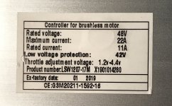
The problems I keep encountering are, either the controller isn't the same or higher specs as mine (48v 750w 22amp), or the I can't tell from the pictures if it has compatible wiring, even on the rare occasion when there is a diagram.

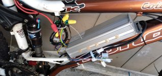
I decided to post a couple of pictures of mine in hopes of someone knowing where I can find a match or upgrade, as I wouldn't mind buying a controller with an upgraded display, but that is definitely optional.

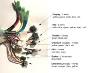
controller-label.jpg
controller-wires.jpg
 
rick_p said:
I...or I can't tell from the pictures if it has compatible wiring....

This is not a realistic expectation, so if it's part of your criteria, then outside of purchasing a full kit, you have a lot better odds playing roulette. Buy based on the specs you want, then just cut the connectors off your old controller and replace the ones on the new, for a quick fix.
 
E-HP said:
This is not a realistic expectation, so if it's part of your criteria, then outside of purchasing a full kit, you have a lot better odds playing roulette. Buy based on the specs you want, then just cut the connectors off your old controller and replace the ones on the new, for a quick fix.

I'm totally fine with that, but how will I know if I'm wiring it correctly when the new controller doesn't have all the same color wires, or even have the wires that are the same color in the same locations in the connectors?
 
You've narrowed the problem down to a lack, or loss of a proper reference or signal voltage in the motor's BLUE hall sensor wire.

.09vdc verses 3vdc.

Which boils down to...

A: Full voltage ( 3vdc) is not making it to your test point. E.G. Bad controller output, wire or connection.
B: Shorted wire or defective hall sensor.

Test very carefully trying not to disturb any intermittent shorts or opens, sneak up on it! :wink:
Test with the meter's BLACK lead on a convenient 0vdc battery or ground location.

Do you have the same low voltage on BOTH sides of the BLUE wire hall sensor connector? If no, you have a bad connection.

If yes...
With the meter's RED test lead on the controller side of the hall connectors BLUE wire. Does the voltage go high (3vdc) when the connector is pulled apart?
If yes... This would indicate a shorted wire, or bad hall sensor on the motor's side of things.
No would indicate a bad controller, wire, or pin connection.

I wouldn't want you to go to all the trouble of a controller replacement, only to find the problem lies elsewhere. Hang in there!
 
Be vewy vewy qwiet while you sneak up on them🤣

unnamed (1)~2.jpg

Re controller wires, the hardest one is usually matching an existing display...
If you don't care about a display, or PAS regulation, or voltage indicators, or anything much besides the power circuit... Then controller matching can be just a few wire nuts away!🤣
IMG_20210304_090428895.jpg
 
TommyCat said:
A: Full voltage ( 3vdc) is not making it to your test point. E.G. Bad controller output, wire or connection.
Note that in this particular case, it also means the hall signal (even if you added an external voltage) is almost certainly not making it to the controller itself. (which you cover checking for in your good testing instructions, but I wanted to point this specific thing out.)
 
TommyCat said:
You've narrowed the problem down to a lack, or loss of a proper reference or signal voltage in the motor's BLUE hall sensor wire. (.09vdc verses 3vdc.)

Which boils down to...
A: Full voltage ( 3vdc) is not making it to your test point. E.G. Bad controller output, wire or connection.
I am highly suspicious of the controller at this point.

B: Shorted wire or defective hall sensor.
I sincerely believe this has been ruled out by the extensive testing I did using the AC adapter as the power source with the Voltmeter and inline resistor. It was rock solid.

Test very carefully trying not to disturb any intermittent shorts or opens, sneak up on it! :wink:
Test with the meter's BLACK lead on a convenient 0vdc battery or ground location.
I was very careful and did test with the meter's BLACK lead on a convenient 0vdc battery or ground location.

Do you have the same low voltage on BOTH sides of the BLUE wire hall sensor connector? If no, you have a bad connection.
Ah, I did not test for this, and that is a good point, I should test one more time before replacing the controller. It would be a waste of time and money to simply miss a bad connector.

If yes...
With the meter's RED test lead on the controller side of the hall connectors BLUE wire. Does the voltage go high (3vdc) when the connector is pulled apart?
I will have to find out when I run the test again.

If yes... This would indicate a shorted wire, or bad hall sensor on the motor's side of things.
Or just a bad connection inside the connector. I really think I've ruled out the problem being on the motor side, but anything is possible. In fact, one thing I could try is testing the Hall sensors with the Voltmeter and AC adapter method after I get the problem to occur.

No would indicate a bad controller, wire, or pin connection.
One of these seem the most likely at this point.

I wouldn't want you to go to all the trouble of a controller replacement, only to find the problem lies elsewhere. Hang in there!
I agree, that would be a huge waste of time and money.

Voltron said:
Re controller wires, the hardest one is usually matching an existing display...
If you don't care about a display, or PAS regulation, or voltage indicators, or anything much besides the power circuit... Then controller matching can be just a few wire nuts away!🤣
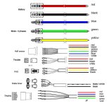
Good point! I think what I'll do is create a diagram of the wiring harnesses configuration on the bike to simplify matching things up with a new controller. You and @E-HP are right, finding an exact replacement with matching connectors is like finding a needle in a haystack, it's best to just find one with the right specs and use my connectors. I contacted the bike manufacturer and they don't have any either.
 
I found an existing diagram online and modified it to match the harnesses on my bike. I don't have and LCD display, just a basic LED model, so if I find that I need to replace the controller, finding one that has the right specs and compatible wiring shouldn't be difficult.
bike-harnesses.jpg
Not all controllers I see for sale have 6 wires for the Hall connector like mine does, many only have five, does anyone know what the white wire is for? In one diagram I found it looks like it might be a "speed sensor." If so, does that mean it's for the speedometer readout to an LCD display that supports it? I'd like to figure that out because if I don't need to find a controller that has all 6 wires, there's a lot more to choose from.
 
You only need the 5 hall wires for the motor to run. Most controllers use a hall signal to calculate speed. The white wire is most likely a temperature sensor. You could try measuring resistance from the white wire to the black wire going to the motor. Typical temp sensor is around 10k ohms. Some cruder models just use a thermostatic switch that cuts the power when it gets too hot.
 
fechter said:
The white wire is most likely a temperature sensor. You could try measuring resistance from the white wire to the black wire going to the motor. Typical temp sensor is around 10k ohms.
I’m getting 4.7 ohms of resistance between black and white wires going to the motor, but while I was set up to check this I also ran the test @TommyCat suggested and found the problem. I’ll post all about that before the end of the day.
 
Re the white wire, I've worked in a few brands where it is the speed sensor, and when running without it hooked up, would make the controller shut after 5 minutes of being on, whether the bike was in motion or not.. That was a weird one to track down the first time.
 
Voltron said:
Re the white wire, I've worked in a few brands where it is the speed sensor.
I'm going to need a new controller, so I'll be sure to buy one that has all 6 wires for the Hall connector. I'll explain how I now know it's the controller in my next post.
 
Back
Top