jonescg's NEW electric racebike BUILD thread!

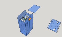
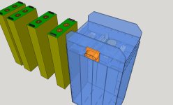
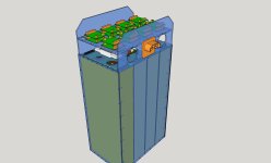
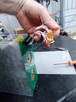
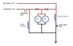
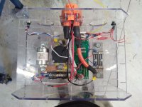
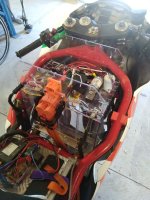
I've decided to move the contents of the main control box to the inside of the main battery enclosure. This way the current shunt, pre-charge and discharge resistors, HV relay and main contactor (and fuse) will all be inside the battery enclosure.
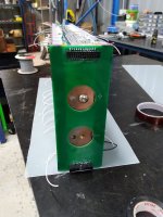
It means designing a more compact PCB to mount stuff on, but this is no big deal. Then I can replace the current (slightly dodgy) Anderson connector with a more appropriate Amphenol HVIL connector.
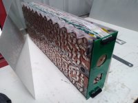
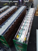
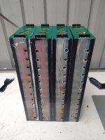
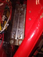
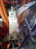
There's still room for the BMS boards above this shelf, but it's going to be tight.
 
Much more compact layout for this PCB. Hope I can get it fabricated in a couple of weeks...
Compact precharge board layout.PNG
The hand-drawn lines indicate where the leads and ring-lugs go.
 
Enclosure is mostly taking shape too. I will probably put a low current HVIL connector just above the big one so I can charge the bike.
 

Attachments

  • Cylindrical pack enclosure assembled 1.jpg
    Cylindrical pack enclosure assembled 1.jpg
    260.3 KB · Views: 9
  • Cylindrical pack enclosure assembled 2.jpg
    Cylindrical pack enclosure assembled 2.jpg
    406.1 KB · Views: 9
Model looks OK. Just have to wait and see how the polycarb fabrication goes.
I also have to find a solution for charging the battery when it's in the bike. I don't want the main contactor needing to be closed when the bike is on charge, but I also don't want live pins on a connector either. So there's the option of a small contactor inside the battery pack, where I have virtually no room left. I'll probably end up using another low current HVIL connector, but even they are so bulky.
 

Attachments

  • Cylindrical pack enclosure fully assembled.jpg
    Cylindrical pack enclosure fully assembled.jpg
    256.6 KB · Views: 8
Why do you like the HVIL connectors better than the Anderson's? I've always used Anderson's and have zero experience with the HVIL system.
 
Why do you like the HVIL connectors better than the Anderson's? I've always used Anderson's and have zero experience with the HVIL system.
Because I'm running a system voltage which exceed the Anderson's limit of 600 V DC.
Plus I also teach HV battery safety, and I don't want to be a hypocrite, even though I'm sure the Anderson would work just fine.
The benefit of the HVIL connectors is that I can arrange it so no power is available on either the main connector OR the charge connector unless something is plugged into it. Considering the charge port will only be accessible with the tank cover off, and the bike is unrideable in that state, I'm not too worried about ride-offs.
 
That makes perfect sense and is something all racing organizations should require for HV systems to ensure worker safety to the greatest extent possible.
 
End cover PCB's finally arrived. I'm not leaving myself much room...
The balance wires have clearance but I will try and use some of that non-adhesive epoxy to settle everything down.
 

Attachments

  • 20231014_182348.jpg
    20231014_182348.jpg
    200.7 KB · Views: 26
  • 20231014_182403.jpg
    20231014_182403.jpg
    232.6 KB · Views: 27
Starting to take shape. It's not the most elegant solution, but it does appear to work.
 

Attachments

  • Header to BMS connector.jpg
    Header to BMS connector.jpg
    157 KB · Views: 37
  • 20231015_171207.jpg
    20231015_171207.jpg
    191.2 KB · Views: 37
Portholes are for squeezing potting compound into. Unfortunately, there's about 2 kg worth of FR4 sheet here already! The potting compound will no doubt add at least 5 kg to each module if I got too carried away, but the main purpose for potting the sides is to secure the balance wires, and preventing them from rubbing or fretting where they shouldn't.
And yeah, Ideally I'd use female headers for the balance wire connections, but this was the most compact option available at short notice. All female PCB mounted headers were really tall and bulky.
Next up, once I have glued the sides on, spotwelding both sides. Sparkletime!
 

Attachments

  • Balance wires and header.jpg
    Balance wires and header.jpg
    88.3 KB · Views: 35
  • portholes for potting.jpg
    portholes for potting.jpg
    286.6 KB · Views: 34
  • Side covers on.jpg
    Side covers on.jpg
    53.9 KB · Views: 33
Wow, that must have been a lot of work!
It is and it isn't. I only work on this over the weekends, and I've got plenty of experience building them now, so I know what to expect. The slow part is spotwelding these tabs, which will take a bit longer since each pulse is longer and the hand piece will get quite hot.
Then the joys of gluing it all together within the tolerances I've set myself.
The polycarb enclosure is being CNCd at the moment, and it should come together fairly quickly. Perhaps not in time for the expo (Nov 4th and 5th).
 
Just a Sunkko 709 transformer welder. Seems to do a pretty good job.
 
Busy day welding a module up. A friend came and lent a hand with his welder too. Duty cycle was famously poor, hance the ventilation. Next step is to glue the covers on.
Shame it won't be rolling in time for the expo, but that's okay. The bike will still be there.
 

Attachments

  • 20231028_160427.jpg
    20231028_160427.jpg
    280.8 KB · Views: 31
  • 20231028_165729.jpg
    20231028_165729.jpg
    218.8 KB · Views: 31
Glued the first side on - keeping it secure with about 40 kg of cobalt sulphate solution.
 

Attachments

  • 20231028_203928.jpg
    20231028_203928.jpg
    103.4 KB · Views: 7
Just a quick update - I've spotwelded all four modules and have glued the sides onto three of them. I fear I will only have enough thermally conductive epoxy resin to glue half a module together. This black stuff from U-sheen is a great adhesive, and the new stuff I got from Electrolube (still laugh at that name) simply doesn't stick to anything. I might be able to put the last of the adhesive around the perimeter of the surface and use the not-so-sticky stuff in the middle? Not keen on mixing them in case they behave weird.
Anyway, the polycarb enclosure should be done this week so I can start to put all the other parts together.
 

Attachments

  • 20231029_114626.jpg
    20231029_114626.jpg
    92.7 KB · Views: 18
12 kWh complete. All up it's 68 kg for these four modules, and the enclosure + hardware will probably add another 7 kg at least.
I can build the battery pack and have it operational, minus the BMS which is yet to be devised. Next weekend will be a productive one!
Tonight when it cools down a bit I might put some of the expanding foam in all the port holes to secure the balance wires. Fully potting it would add at least another 3 or 4 kg, so I'll avoid that if I can. For a road-going EV, sure. But not a racer.
 

Attachments

  • 4 modules complete iso.jpg
    4 modules complete iso.jpg
    177 KB · Views: 15
  • 4 modules complete top.jpg
    4 modules complete top.jpg
    153.1 KB · Views: 15
  • 4 modules complete.jpg
    4 modules complete.jpg
    86.9 KB · Views: 15
It's an inline 4!
20231119_174455.jpg
Minus the enclosure and other hardware...
 
Bit of progress on the battery today. Rather warm in the shed though. 42'C in November is a record broken.
Test fit of the enclosure went well. Bit tight at the base, but I can make adjustments if needs must.
Enclosure test fit in bike.jpg
The charge HVIL and discharge HVIL are mounted, while the modules themselves fit snugly in the space provided.
HVILs installed.jpg
I'm not sure if the fans will fit now that everything is coming together. I might proceed with some covers and see how we go.
 
HVIL contactor and fan logic sorted:
 

Attachments

  • Fan and HVIL circuits.jpg
    Fan and HVIL circuits.jpg
    40.7 KB · Views: 8
Every day is like a puzzle... once it's done I'll devise a better way of doing it.
 

Attachments

  • 20231203_165158.jpg
    20231203_165158.jpg
    244 KB · Views: 15
Pack fixings in place. Most of the HV wiring is done, but there's still a few bits to finish.
 

Attachments

  • 20231209_112844.jpg
    20231209_112844.jpg
    252 KB · Views: 16
  • 20231209_112822.jpg
    20231209_112822.jpg
    177.2 KB · Views: 16
  • 20231209_112546.jpg
    20231209_112546.jpg
    198.6 KB · Views: 16
Back
Top