Kepler Friction drive comes of age.

The arduino would be a great solution. Unfortunately my experience with arduino is limited but if anyone is interested in designing an arduino solution that will do the job, it would be great for the ES community.

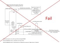
You would need the device to do the following steps

Start drive sequence:
1) Activate assist through a push button (a wireless button would be ideal but not sure if there is a solution currently available)
2) Servo drives full sweep and allows the motor to make light contact with the tire.
(Due to the sensorless nature of the controller, its good to have the motor turning before the motor is activated)
3) Once the servo has gone full travel, Throttle signal is sent to the controler (0.8V = zero throttle 3.8V = full throttle)
Throttle should be ramped from 0.8V to 3.8V over a 2 second period (time period might need tuning)

Stop drive sequence:
1) Activation push button is released
2) Servo drive full opposite sweep to fully reduce tension on pull cable.
3) Throttle signal is ramped down from 3.8V to 0.8V over a 2 second period

Anyone who can design and build an operational microprocessor drive activation unit that they are then willing to build and sell or alternately make the design and code available to the ES community gets a free Drive Mech sent to them.
 
For now though we need a basic solution to activate the controller and drive the servo that most of us can achieve. This is what I came up with.

Edit: (Wiring diagram deleted due to not being successful)

If you can use a soldering iron, you will be able to make this activation interface. I will lay it out on Veroboard in the next day or 2 to make assembly nice a neat.

Below are the modifications I did to the servo tester. I can't guarantee the mods will work on any servo tester but i can't see why they shouldn't. I have order a couple of simple servo testers from Hobbyking to test though
 

Attachments

  • Servo tester.jpg
    Servo tester.jpg
    154.3 KB · Views: 3,741
  • Servo tester1.jpg
    Servo tester1.jpg
    142.7 KB · Views: 3,741
Just back from the electronics supplier picking up components. Decided to use 2 reed relays rather then a single double pole relay. Below is the modified wiring diagram. Should have the Veroboard layout sorted by the end of the day.
 

Attachments

  • Friction Drive activation wiring diagram fail.jpg
    Friction Drive activation wiring diagram fail.jpg
    53.9 KB · Views: 3,648
Hi,

Really nice mechanical design there. Nice to see how this system keeps on getting better. Although I'm less charmed by the latest evolution of the mounting position of the servo actuator. The nice thing about the whole design is that you only need one simple and universal mounting position around the bracket. Now that you need a second fixation point for the servo actuator it looses some of its simplicity. What about compatibility? bicycles with a shifter in the front have no room left there I can imagine. I think this will be hard to sell in a commercial product.
It would be nice if the servo could be mounted on the bracket plate itself, somewhere under the BB, combined with some sort of cable guide roller, mounted above the outrunner motor. I do realize though space is very limited...
It'remains a pitty that the pure mechanical solution with the spring didn't work out...

Kind regards
Pascal
 
1 step forward, 2 steps backwards today. Built the circuit and tested. Found that the 5V supply from the controller didn't have a enough headroom to run the servo tester and servo. Bugger, probably should have predicted that. So it looks like I will need a second regulated power supply to power the servo and servo tester. Got some ideas already for this but a job for another day.

So time for a change of tact.

I have had a number of requests to incorporate a "zero gravity spring" with this design. I have resisted this due to it being fiddly to setup and not the most reliable method of activation. Also I didn't want to complicate the design after working so hard to keep the design as efficient and minimalist as possible. However, I have reluctantly conceded and have managed to come up with a solution that is easily adjustable and only adds 3 extra parts to the drive. The addition of this zero gravity spring will be offered as an optional extra and will add $10 to the cost of the drive if opted for.

I have opted for a torsion bar type spring bent from 1.5mm piano wire. Adjustment is straight forward. Once end point adjustments are complete and torqued down, the centre bolt can be loosened off and spring tensioned by rotating the final disc in the stack.

All fitted to my road bike ready for testing tomorrow. should be interesting to see if I can get a good reliable engagement.
 

Attachments

  • 20161227_152924.jpg
    20161227_152924.jpg
    89.1 KB · Views: 3,651
  • 20161227_152945 (1).jpg
    20161227_152945 (1).jpg
    61.9 KB · Views: 3,651
  • 20161227_163225.jpg
    20161227_163225.jpg
    112.1 KB · Views: 3,651
The arduino steps above are pretty easy to nail on a ten buck nano kep. The programs that cone standard in the arduino library would need little modification. I'm strapped for time with my return to work but I have a buddy who could do it fast. Will send you a msg.


Sent from my iPhone using Tapatalk
 
I was testing my servo tester it has a sweep function and a center function. The center button moves the servo to center as the motor is brought to half throttle. The sweep function ramps up motor to full very smooth while fully sweeping servo all wth one button. BUT it's function is to sweep back Down again. If you push that button again it shuts down but pot can take over. Also has exercise mode which cycles pulse width between 1000 to 1500 then 1500 to 2000 then back. Not sure if this thing could be modified but would easily be handle bar mounted and just use long servo extensions with y at end. It's a 37 mm square 20 mm thick. Bought at local hobby shop for around $20. Just thought I would share that info. Model is a email or electronic model systems precision servo driver.
 
Anyone got a servo they are willing to depart with for free/cheap? I haven't used RC stuff in a while :lol:

Happy to have a go at this, but if I order a cheaply it will take a while before its here...
 
Cool, can pop by tomorrow night after work if you would like. I'll have a dig, I'm sure I ordered a bunch of arduinos a while ago. If you can find two servos the same and I can find you a spare arduino, then if I put the code up here you can also access/test? This is starting to sound like a plan which might work :shock:
 
Tested the drive today with the "zero gravity spring". Was pleasantly surprised to find that drive activation was very positive and consistent. got me re thinking the need for active engagement after all. :oops:

I think the main difference is that the drive position is very adjustable and as such I could accurately position the drive to pick up the tire under torque kick action.

Installed a neat button throttle next to left-hand shifter and ran the wiring internally through the frame.

20161228_190034.jpg

20161228_185954.jpg


This then went to a voltage divider and in turn to the controller.

The only real issue is that on shut down, the drive disengages with a thump and could do with a motor ramp down to soften this.


I will try a capacitor across the throttle signal into the controller and ground to hopefully bleed off the speed more slowly.

Will test this tomorrow.
 
Lurkin said:
Cool, can pop by tomorrow night after work if you would like. I'll have a dig, I'm sure I ordered a bunch of arduinos a while ago. If you can find two servos the same and I can find you a spare arduino, then if I put the code up here you can also access/test? This is starting to sound like a plan which might work :shock:

Sounds like a plan. Just shoot me a text first. See what we can com up with.
 
First off, this drive is so simple and elegant!

I saw your post, and I've already been working on some servo ramping code for my esk8.
Put together a quick test circuit and made some nice progress. :D

The circuit is just a nano clone and a single button.
I have rf remotes for my board so going wireless is pretty simple but I think a single wire is much cleaner.

https://www.youtube.com/watch?v=R6sP3EaxQaA

looks like you may have eliminated the need for a servo already, but the ramping is still something.
and a VESC would be great on one of these. with FOC on a hub motor it is silent. 8)
 
The fusion of the latest skateboard tech and this friction drive is in my opinion what is going to take friction drives to the next level.

My skills lie in mechanical engineering however as you can see motor controller skills are rudimentary.

I am so keen to fit a VESC to this drive system in FOC mode.

I know small skateboard hub motors are available but all seem to be too low in rpm and i need to keep the diameter down to 70mm. my target speed is 45 kph (28mph). So can this be done with a 70mm skateboard hub motor?

Also, do need to run a skateboard hub motor sensored to get silent FOC mode operation?

Keep in mind the dynamics of a friction drive is that the speed the bike will do with the the motor driving the bike wheel is same as the speed the motor would do directly on the ground if fitted to a skateboard. It makes no difference what diameter the bike wheel is also. The bike will do the same speed regardless.
 
Excellent thread. I'll be watching with great interest.
 
I just used the hub motor as an example, most are just 6355 or 6374 stators.
the vesc works great sensorless! so much that I haven't bothered to try sensors. what esc are you using now?

im not sure what you mean by the speed being the same, the wheel/motor make a reduction, so changing size will change speed/torque just like belt drive.

anyways if the servo setup in my video will work for you, let me know and i'll post the code and make a schematic. 8)
 
Thanks Saul. The ramp looks great driving both those servos. Perfect for an RC type ESC setup and I presume for a vesc setup too. Hold off on releasing the code as i have a few new ideas and as you can see from my previous post, taken a bit of a different direction. Also a 1V to 4V output for a standard bike controller is needed for a standard ebike controller rather then a servo output.

im not sure what you mean by the speed being the same, the wheel/motor make a reduction, so changing size will change speed/torque just like belt drive.

The concept is a little confusing but the dynamics of a friction drive mean that it makes no difference to the speed of the vehicle if the was roller was directly on the ground, on a 20" wheel, or 700c road bike wheel. Vehicle speed stays exactly the same. Think about it.
 
So I built a new button throttle interface today with ramp down to stop the thump on shut down.

Here is what I came up with. Tried a few different sized capacitors and settled on a 1000 uf Electrolytic. This gives me a 1.5 second ramp down and a nice soft disengagement.

This has worked out to be a very satisfactory solution. With the addition of the zero gravity spring and this simple button interface with soft ramp down, the drive can now be interfaced to a cheap ebike controller with minimal setup an effort.

Button throttle interface with rampdown.jpg

Button throttle interface with rampdown1.jpg

button throttle5.JPG

button throttle5 Verboard layout.JPG
 
Dude you totally went analogue on that solution. Haha I gotta stop thinking arduino for everything.


Sent from my iPhone using Tapatalk
 
Also a 1V to 4V output for a standard bike controller is needed for a standard ebike controller rather then a servo output.

you could use a digital pot to get a ebike output
https://www.sparkfun.com/products/10613

As stealthy as this is, you need a VESC on FOC and you really freak people out silently flying by, probably even yourself. :pancake:

that analog solution is really nice tho!
 
Hi Kelper, Can I get on the list to buy a set when they are available? I sent you a PM, but would email be preferred?
 
Back
Top