Kepler Friction drive comes of age.

More testing with analog button and gravity spring today but this time with a 63-74 motor. Wanted to see if the heavier motor would have trouble engaging reliably. No problems at all. Engaged perfectly every time and smoothly disengages with the 1000 uf capacitor doing its job nicely.

So now i have a have a dilemma. The 63mm motor performs better then the 50mm but is heavier and more visible. Need to decide which I prefer.
 

Attachments

  • 20170103_133258.jpg
    20170103_133258.jpg
    120.7 KB · Views: 3,365
  • 20170103_171135.jpg
    20170103_171135.jpg
    143.1 KB · Views: 3,365
I vote for the 63 seems like it would be smoother than the 50.
doesnt really show up that much on bike IMO.
I have gotten myself a beginner arduino uno kit. Trying to learn and it is very easy to learn with this kit.
I cant quite get it to work right with the motor. the servo sweep with push button works well with servo. just copied the sketch then ran it it with arduino hooked up. Then took the arduino and breadboard, hooked up the y harness to control both servo and motor. but it cuts out and turns the speed control off. then on again. The reason I am mentioning is that I think with all your talents you could figure out the arduino program quickly and have that servo engagement going. it is really a cool concept and an arduino micro hooked up to a esc would be so sweet. it could be a one button throttle control (longer you hold it and the faster the motor goes and motor engagement via servo. I think if the low end is modified so the button only lowers it to a small voltage and keeps the motor from power cycling it would work. maybe but I am a total amateur at this stuff.
I am going to keep tinkering but hopefully this will prompt another to figure out much quicker than I and post the sketch. I bet it is not very difficult of a concept.
what I was going for is a roughly 4 position speed switch low, med, high then off. I figure with some configuration of that you could have a tun able speed control with one small momentary button(switch) leaving a very stealth handlebar.
 
meant to say by tune able I meant via the arduino programming. you can change the speed it moves the servo arm and to what angle between o and 180 so seems like with proper y hookup the motor would perform the same therefore allow experimenting via software changes. litterly a couple of number changes then re compile the programming changing what the arduino tells the servo and speed control what to do.
 
mhaskell said:
In which way does the 63 perform better than the 50?

The 63mm has more torque for the sam power input. Low speed on hills is where the 63mm really shines. At high speed, there is not much difference. The 63mm has a lower pitch whine then the 50mm also.
 
telcosteve said:
I vote for the 63 seems like it would be smoother than the 50.
doesnt really show up that much on bike IMO.
I have gotten myself a beginner arduino uno kit. Trying to learn and it is very easy to learn with this kit.
I cant quite get it to work right with the motor. the servo sweep with push button works well with servo. just copied the sketch then ran it it with arduino hooked up. Then took the arduino and breadboard, hooked up the y harness to control both servo and motor. but it cuts out and turns the speed control off. then on again. The reason I am mentioning is that I think with all your talents you could figure out the arduino program quickly and have that servo engagement going. it is really a cool concept and an arduino micro hooked up to a esc would be so sweet. it could be a one button throttle control (longer you hold it and the faster the motor goes and motor engagement via servo. I think if the low end is modified so the button only lowers it to a small voltage and keeps the motor from power cycling it would work. maybe but I am a total amateur at this stuff.
I am going to keep tinkering but hopefully this will prompt another to figure out much quicker than I and post the sketch. I bet it is not very difficult of a concept.
what I was going for is a roughly 4 position speed switch low, med, high then off. I figure with some configuration of that you could have a tun able speed control with one small momentary button(switch) leaving a very stealth handlebar.

Just keep in mind the addition of the gravity spring has negated the need for a servo to mechanically engage the drive. Keep working on the motor activation, multiple speeds, soft rampdown though. :)
 
A few more tweaks to the design. I have now removed the chain stay extension on the BB mounting plate. I found it really wasn't doing that much. I haven't used a cable tie on chainstay for ages and have never had any slippage issues. I have also extended the range of adjustment to suit a greater variety of bikes and to better match the 63mm motor. The 50mm motor still fits fine also. In addition to this I have a skateboard hub motor wheel coming to try out. It is 70mm in diameter and is not an RC style motor. I have selected the highest RPM I can get but it still may be too low for an ebike. Hoping some over volting may help here.

In relation to understanding if the drive will fit your project, I have put together a few diagrams to illustrate the drive geometry on bikes of different chainstay length.

The critical dimension is the distance from the centre of the bottom bracket, to the face of the tire. The drive is adjustable enough to handle a distance of 60mm to 90mm
 

Attachments

  • 63mm geom1.JPG
    63mm geom1.JPG
    46.4 KB · Views: 3,312
  • 63mm geom2.JPG
    63mm geom2.JPG
    51.2 KB · Views: 3,312
  • 63mm geom3.JPG
    63mm geom3.JPG
    49.6 KB · Views: 3,312
  • 63mm geom4.JPG
    63mm geom4.JPG
    98.5 KB · Views: 1,914
Kepler,

You mention 7s 18650 and 6s Lipo for the SK3-5065-236.
What would be recommended for the SK3-6354-260.

All new to me...

Thanks!

T
 
Kepler said:
Same battery combos will be fine.
Thanx this will be my LiPo bike. Have all the kit. And this will be an errand bike, and I think it'll be incredibly stealthy visually. Like yours. It's so minimal. I fret over the electronics. But it'll be fun.
 
Thanks for posting the distance of the bottom bracket to wheel contact. For awhile I would look at all the lightweight road bikes on Craigslist and a keen observer would notice that road bikes vary a lot in this measurement. This would leave me confused to whether your drive would work on that bike. Now I know :wink: . My next trip to the local bike shop will be with a measuring tape in hand. Sales folks will be: "WTF is this guy doing." My response: "Oh. I'm just fitting the bike to me!" :lol:
 
Design tuning continues.

In an effort to make the drive fit a greater number of bikes, I have now pushed out the bottom bracket centreline to tire face out to a maximum of 110mm with a 63mm motor. This now gives me a range of 50mm which is about all I can squeeze out of it.

I have added an adjustment extension finger on the zero gravity spring tensioning disc. This make adjustment of this parameter much easier.

I mentioned a few post back that the chain stay extension on the BB mounting plate was not required and had been removed. I was wrong, it is needed. Following a few extended test rides, i found that under certain conditions, the drive could move on the bottom bracket.

However, due to the great adjustability of the drive, i have found I also need to have an adjustable chain stay extension arm. I really didn't want to add the extra complexity and associated cost to the drive however, the chain stay extension is required so no choice in the matter. Good news is that the parts count is still the same due to the deletion of spare different length swing arms. The extra adjustability means I can now use one length swingarm regardless of motor or measurement. Also means I can keep the price the same.

Once i have the new prototype parts tested and i am happy with them I can start filling some orders. Thanks all for your patience. I am sure you understand I want this drive to be the best it can be. :)
 

Attachments

  • 63mm geom110mm.JPG
    63mm geom110mm.JPG
    60.8 KB · Views: 3,150
  • Fiction Drive Mk4.JPG
    Fiction Drive Mk4.JPG
    27 KB · Views: 3,150
  • Fiction Drive Mk4-1.JPG
    Fiction Drive Mk4-1.JPG
    29.6 KB · Views: 3,150
For anyone who can't wait and has a bike with geometry between 60mm and 85mm (Centre BB to tire face) I have 3 new previous prototype drives I am willing to sell at a reduced price. These drives will come complete with a zero gravity spring and 3 different length swingarms to help fine tune the fit to your bike.

Asking $50.00 USD each. Postage is $15 USD to USA.

I have a box full scrapped prototype parts however these drives are to far developed to be scraped. I will use to funds to pay for the next set of prototypes.

Please PM if you are interested. First in, best dressed.
 

Attachments

  • 20170106_112653.jpg
    20170106_112653.jpg
    94 KB · Views: 3,143
I missed your PM. Sorry about that. And definitely no issues :) With regards to Titanium, never even considered it. I could get a price but i doubt the laser cutting company I use would have Titanium plate in stock sheet in stock. I can ask the question though if you are serious.
 
I am considering converting my wife's bike to a friction drive but am pretty much clueless about the parts that are needed and where to get them. Since you have experimented with various motors, throttles, controllers,batteries, ect it would be helpful if you could provide a list of components that you feel are the best for a beginner. If I understand this correctly what you are doing is taking a motor and fixing the the shaft so that the motor body turns. Is that correct? If so doesn't the friction of the tire and whatever the tire picks up from the ground damage the case of the motor? I have found your detailed progress of the project very interesting.
John
 
I am putting together a list of parts for a cheap basic build. Also putting together a manual detailing assembly and setup.

With regards to the motor, the drive uses an Outrunner motor. This is a very common type of RC style motor that has both the outer case and shaft spin with the stator section of the motor being held stationary and attached to the drive swing arm. https://en.wikipedia.org/wiki/Outrunner
 
Kepler said:
I am putting together a list of parts for a cheap basic build. Also putting together a manual detailing assembly and setup.

With regards to the motor, the drive uses an Outrunner motor. This is a very common type of RC style motor that has both the outer case and shaft spin with the stator section of the motor being held stationary and attached to the drive swing arm. https://en.wikipedia.org/wiki/Outrunner

Thanks. I think this may be perfect for my wife. She only rides occasionally and always on paved flat surfaces. Some torque would be nice for getting across busy streets when there is a break in the vehicle traffic.
 
hi Kepler and everyone else apparently:)
sorry for the newbie here but I cant pm for some reason it just goes to the outbox. anyhow I am interested in buying a prototype but dont know how to tell you.
let me know or PM me so I can try to communicate better.
Thanks
Steve
 
Kepler, did you find it necessary to cut the shaft on your 63 motor? It looks like mine sticks out too far on the one side. If so any suggestions how to cut it shorter to prevent from hitting crank arm.
 
Kepler-
Looking forward to the bracket- I think you have designed a beautiful solution for those looking for a little help without transforming the bike. While I am not going for the cheapest setup I think it may be the easiest electronic setup to balance with your simplified elegance.
Here is a breakdown of what I am planning:
I will be using a VESC with the nano hand held throttle controller along with the sk3 6354 260kv motor- initial testing will be with 2 4s 6600 mah batteries in series since I already had those ( but expect to ultimately use 18650 batteries in a 7s configuration)
My intent is to design and print a water bottle using petg filament that will be able to hold both batteries, receiver and vesc and just drop into a waterbottle holder on the seat tube. Initially it will be hard wired but the intent is to be able to have it be as simple as sliding in or removing the "bottle" so that I can take the batteries and esc with me if locking it up somewhere- similar to mounting a battery bracket like a shark pack. As for the hand held remote I am planning on designing and printing a new "housing" that would allow me to mount it on the handlebars as a thumb throttle.

I have just received the vesc and remote so time to start "drawing it up" and hopefully sharing my progress
Scott
 
luvtobike said:
Kepler-
Looking forward to the bracket- I think you have designed a beautiful solution for those looking for a little help without transforming the bike. While I am not going for the cheapest setup I think it may be the easiest electronic setup to balance with your simplified elegance.
Here is a breakdown of what I am planning:
I will be using a VESC with the nano hand held throttle controller along with the sk3 6354 260kv motor- initial testing will be with 2 4s 6600 mah batteries in series since I already had those ( but expect to ultimately use 18650 batteries in a 7s configuration)
My intent is to design and print a water bottle using petg filament that will be able to hold both batteries, receiver and vesc and just drop into a waterbottle holder on the seat tube. Initially it will be hard wired but the intent is to be able to have it be as simple as sliding in or removing the "bottle" so that I can take the batteries and esc with me if locking it up somewhere- similar to mounting a battery bracket like a shark pack. As for the hand held remote I am planning on designing and printing a new "housing" that would allow me to mount it on the handlebars as a thumb throttle.

I have just received the vesc and remote so time to start "drawing it up" and hopefully sharing my progress
Scott

i recommend to use lower kv motor(if you still didn't buy it)
with 6374 170 kv 6s battery i get 50km/h
with 6354 260 kv 8s battery with my calculations you will get 84,6982656km/h (32volts) (it with no load on the wheel )(wheel in the air and you press full speed)
in theory you will get assistance up to 80 km/h but it will be very low torque
you don't need 80 km/h speed but you will need more torque
so use lower kv to get less speed (50km/h no load is ok) and torque will be better
to calculate all use this https://docs.google.com/spreadsheets/d/1fThvw5jWdHG9NMuetc5DPxLFr33oenAE34LP8s6IWec/edit#gid=376121520
gear ratio 1 to 1 (M pully=1 Hub pulley=1)
wheel diameter = motor diameter
with vesc ideal to get 50 km/h with 12s battery
 
A 63-74 doesn't fit the drive so forget that.

As long as you keep the kv under 280 and no greater then 6S LiPo or 7S 18650, you will get a good result regardless of it being a 63mm motor or 50mm motor.

When on the bike, calculated speed is only what you will get close to if you can throw enough amps at it. I use controllers with a current limit of around 14A. This means a 280 kv motor will have a similar real world max speed similar to a 200kv motor because its the current limit that is the governing max speed factor. Also real world torque feels very similar.

With regards to torque, amps-in is the main governing factor, not kv which is why 14A on a 200kv motor or 280kv motor feel quite similar. However, the 200kv motor will run cooler then 280 kv motor. Good news is that at 14A, heat isn't an issue in either case. You also find that a motor with a lower kv has a longer stator and as such is a physically heavier motor. Another reason why a low kv motor will run cooler.

The other governing factor is the speed controller's electrical RPM. The ebike controllers I am using have low electrical RPM capabilities. On 7S 18650, if free spinning, a 230 kv plus motor will cut out at full throttle on an ebike controller. However, under load this isn't a problem as the motor can never get to the electrical max speed anyway.

Different story if you use a non current limited RC controller though. This is where it is important to use match the kv to the speed you want to do more closely.

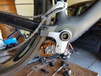
A vesc has current limiting capabilities so the sk3 6354 260kv motor will work fine.

I found these two motors the other day. Both would be a good fit for the drive.

https://www.aliexpress.com/item/Fre...ice=c&mtctp=&gclid=CKG7wqipttECFQsQvQodcjMKyg

https://www.aliexpress.com/item/fre...id=a1306095-143d-4fd1-9e1d-d078c6e341fb&tpp=1

There is a real cross over between skateboard stuff and friction drive stuff which is a good thing. It is really opening up choices for friction drives.

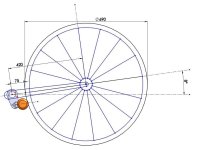
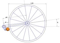
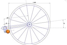
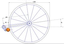
The reason why the cross over is there is because road speed of skateboard wheel is the same as the road speed of a friction drive motor on a tire regardless of wheel diameter.

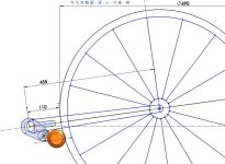
Put another way, if you put 63 mm motor directly on the ground, against a 20" tire, or against 700c tire, the road speed for all 3 examples is always exactly the same. One of the very positive characteristics of a friction drive.
 
Would it be possible to mount an 80-100 to one of these? It just occured to me that I have an 80-100 just sitting here, and I have some lipo and an under-seat bag... Just need another VESC and your bracket.
 
Back
Top