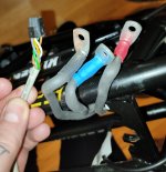
Kuberg Freerider motor wiring

dynz

1 mW
Joined
Feb 18, 2023
Messages
11
Location
London
Not long ago I purchased a defective Freerider. It's a long story. I'm going to be replacing components until it works, starting with the controller. Purchased a Fardriver ND72850 which should get here in a few weeks.

Taking it apart I noticed the wires coming from the motor (which I might replace later) are all different colours from the controller connections I've seen online. So i was wondering if anyone managed to get their hands on a wiring diagram or could explain to me how to wire everything up correctly without opening the motor up, if possible.
 
Can you post a picture of the wires? There should be 3 fat wires and at least 5 skinny wires.
 
That is pretty non-standard. Sorry I don't know the wire colors for that particular motor. Hopefully someone else will.
If you have the old controller, you may be able to figure it out from that. One of the hall wires will be connected to the controller battery negative (ground). One will have 5v on it when the controller is powered up. The remaining 3 are the signal wires. From there, you can use trial-and-error to figure out the mapping See: How to Determine the Wiring for a Brushless Motor or if the new controller has a "self-learn" mode, you can use that.
 
If you remove the plate on the motor you can see it. Its a 5 minute work.
yellow:Hall A
green:Hall B
grey: Hall C
white: GND
brown: +5V

There is no temperature sensor on the motor. I added one on the windings. I am using the motor with Vesc 100/250.
 
Last edited:
If you remove the plate on the motor you can see it. Its a 5 minute work.
yellow:Hall A
green:Hall B
grey: Hall C
white: GND
brown: +5V

There is no temperature sensor on the motor. I added one on the windings. I am using it the motor with Vesc 100/250.
Appreciate that @srapy
 
If you remove the plate on the motor you can see it. Its a 5 minute work.
yellow:Hall A
green:Hall B
grey: Hall C
white: GND
brown: +5V

There is no temperature sensor on the motor. I added one on the windings. I am using the motor with Vesc 100/250.
just wondering would you happen to know how the phase wires line up as well? hope the fardriver gets here soon 😶‍🌫️
 
just wondering would you happen to know how the phase wires line up as well? hope the fardriver gets here soon 😶‍🌫️
In most cases it does not matter how you connect them, just give it a try.
 
Not long ago I purchased a defective Freerider. It's a long story. I'm going to be replacing components until it works, starting with the controller. Purchased a Fardriver ND72850 which should get here in a few weeks.

Taking it apart I noticed the wires coming from the motor (which I might replace later) are all different colours from the controller connections I've seen online. So i was wondering if anyone managed to get their hands on a wiring diagram or could explain to me how to wire everything up correctly without opening the motor up, if possible.
I also just got a Freerider that some fool thought he could "hotwire" as he lost the cutoff magnet. My problem is the wiring for the magnet kill switch. There are 4 wires going to the kill switch that has been removed / lost. the replacement magnet Kill switches
I have seen only have 2 wires. What are the other 2 wires? What 2 wires are the kill switch? any info would be greatly appreciated.
Thank you,
Moto.
 
I Think fixed my own problem, the 4 wire connector I was confused about is for the bluetooth module.
I found the 2 wire cut off switch. 🙏🏻
 
Back
Top