kWeld - "Next level" DIY battery spot welder

Here is the complete document, where it is described why one side is making a getter connection.
Also a lot of other interesting things there to read.
This link was already posted a few posts above.

This does not explain anything.
Page 8 / 464:
The DC (Direct Current) input was applied to one electrode, and ground connection to another electrode. The heat generated at the end of one electrode tip is relatively greater than another tip due to the fact that there is only one direction of current flow as illustrated in Fig. 11 and Fig. 14. The uneven heat distribution on electrodes causes one electrode tip to wear faster than the other.
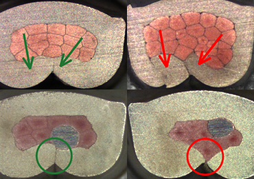
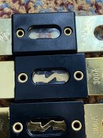
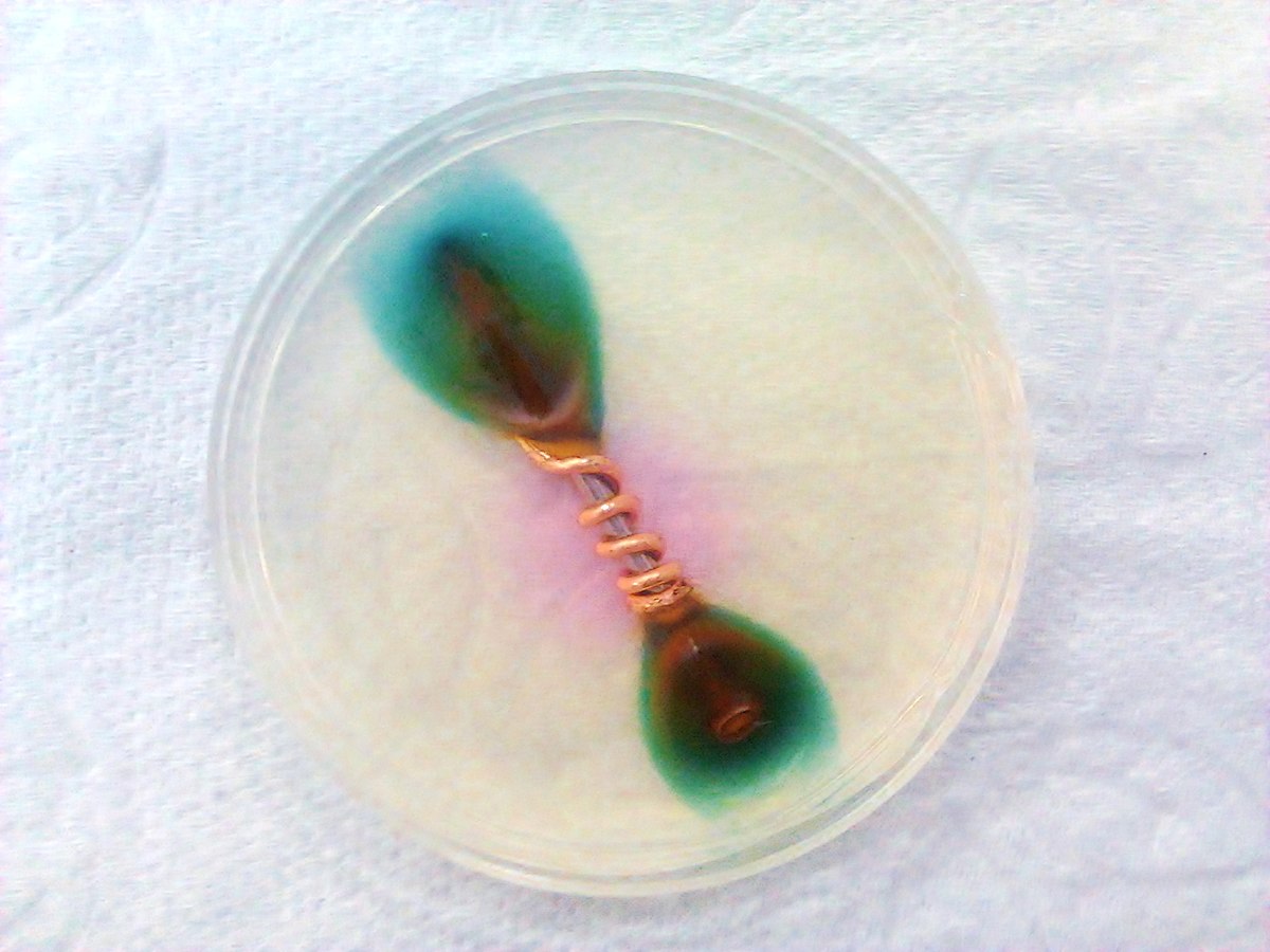
Description - yes, but Schultz describes it as well.

There are at least 2 documents that do some practical explaination of the matter:
The Effects of Polarity on the Resistance Welding Process
Fundamentals of Small Parts Resistance Welding

(no links, everybody can find them)

For example:
In resistance welding, both the weld heat and the size of the weld nugget can increase or decrease depending on the polarity of the current passing through the parts. This is caused by a phenomenon known as “The Peltier Effect”, which is present when the weld current flows in only one direction. The Peltier Effect can be used to help balance weld heat in certain applications. This can be very beneficial when welding parts of unequal thickness or dissimilar composition. Power supply technologies affected by this phenomenon include Capacitor Discharge, one-half cycle AC, Linear DC, and High Frequency Inverter. Although this effect is dominant only in the first few milliseconds of the weld, the increase or decrease of weld heat can be significant and should be considered any time one of these technologies is used.
Shorter cycle - stronger efect.


Now when I weld nickel strips the weaker spot(the one on the positive electrode)is strong and requires enough force to rip it off.
When I weld 0.15Ni+0.1Cu the spot on the negative electrode comes always very strong and difficult to rip off but the spot on the positive it’s not so strong and sometimes it’s ripped off easily.
I tried to use bigger pressure on the positive electrode and less on the negative one and also the contrary but it doesn’t change much.
Is there something that I do wrong or is normal that one spot is stronger than the other?
  1. Longer cycle, which means lower current
  2. Different force, as you already did (But do you measure the difference in force and the force? Use scales.)
  3. Use Nickel plated steel instead of pure Nickel. Allows lower current.
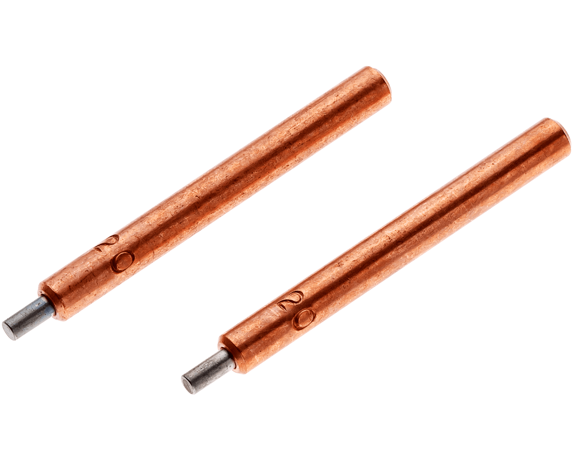
  4. Different electrode material.
 
I plan to sell assembled and tested units (with EMC and safety certification later on) as well as kits. I already have a laser-cut sheet metal enclosure here on my desk, form example. There will be a kit that includes the capacitor module, and also one without.
Thanks. But will the enclosure have the space for bigger capacitors?
Comparing sizes:
Licap SC1200-270-ASC - kWeld Pro picture
D = 60.2 mm
L = 63.2 mm
M12 x 1.75 x 14 mm

Maxwell BCAP2000 P270 K04 - I want to fit
D2 = 60.7 mm
L = 102 mm
M12 x 1.75 x 14 mm
And 3000F ones are around 140 mm in length.
Adding capacitors to kCap is not recommended, the balancers are not very strong. Replacing them would be possible, but in that case wouldn't it be easier to add some other suitable balancer to the pack?

You can use kWeld down to 4 volts, which in most cases will be low enough to get below the 2000A limit.
Thanks again. Got a second kCap instead. Will connect 2 kCap in parallel.
A single kCap at the moment calibrates at around 1300 A and welds at around 1200 A.
 
Thanks @qwertyES !

Different force, as you already did (But do you measure the difference in force and the force? Use scales.)
I used a kitchen scale. The sum of the forces for both electrodes was always 4kg(i press with the pen on the scale until I hear the pen switch going on). I started with 2kg for each electrode and then modified it to be 3kg with 1kg(the maximum difference). I increased/decreased the force on each electrode with 0.5kg at a time.
I use 3.5-4kgf for the daily use.
Unfortunately I don’t have any steel plated nickel. But following @spinningmagnets advice I will stay with 0.1-0.15mm copper sheet. The welds come nice with a lot less stress on the welder and cell tabs(which at high energies start to get punctured especially the negative).

For now I use copper tellurium electrodes, bought them from aliexpress( so not sure if really tellurium ), if I stay under 80j the wear is acceptable.

The part that I like most is that there are no more missed welding spots with blown holes in the strip.

I get a bigger difference than you between cal current and welding current (cal 1700a, weld 1400a).
If I want to weld at 1700a first I have to calibrate the system at a lower power source voltage and then I need to increase the power source voltage when welding.
In the end I replaced the original voltage pot with a multi turn trimmer. I did this mostly because I had some kind of fear that accidentally I will move the original voltage pot thing that could lead to overcharging the caps.
Now is all good and I it’s easier to set a precise output voltage.
Now depends also what you weld, if only nickel you don’t need 1700a and 1400a is good too.

My welder reads 50mv extra for the power source voltage so for 5v it reads 5.05v.
So if I need 5v for the welder, I charge the caps at 5.05-5.07v and set the undervoltage protection at 5v this way if the caps aren’t changed enough the welder won’t work.
Setting the charger 50-100mv higher assures you that at the end of CV(the 5.05v target that we need) will be done at a higher current. If we set to only 5v instead 5.05v it will take longer to charge the caps after each weld.

What I still have to do is add some comparators on each capacitor. These comparators will activate some optocouplers. I can connect the optocouplers in series and then connect the series to the enable of the power supply.
When one cap overcharges it will turn off it’s optocoupler which will disable the power supply output.
With comparators I mean some opamps but thinking better also some cap balancers would work.
 
I used a kitchen scale. The sum of the forces for both electrodes was always 4kg(i press with the pen on the scale until I hear the pen switch going on). I started with 2kg for each electrode and then modified it to be 3kg with 1kg(the maximum difference). I increased/decreased the force on each electrode with 0.5kg at a time.
I use 3.5-4kgf for the daily use.
I use the original electrodes and the force allied is somewhat higher - 6 to 10 kg.
Got the same head as yours from aliexpress, but it's still not in use. Hope to test it soon and compare with you results.
Industrial pneumatic heads go from around 200 g to 10 kg per electrode. This means from 400 g to 20 kg total.

Unfortunately I don’t have any steel plated nickel. But following @spinningmagnets advice I will stay with 0.1-0.15mm copper sheet. The welds come nice with a lot less stress on the welder and cell tabs(which at high energies start to get punctured especially the negative).
So, I have the following setup:
kSupply + kCap + kWeld
At 8.1 V weld current is around 1200 A
0.125 mm Copper + 0.1 mm Nickel plated steel
150 J weld energy

Welds are strong and consistent, but due to the high energy the electrodes heat up quite fast.
That's why I consider going at higher currents, so I can set lower weld energy.

The mechanism of heat generation in the sandwich is that the heat is generated by the highest resistance material.
And that's the Nickel, or the Nickel plated steel. The Nickel plated steel has higher resistance, hence generates more heat at the same current. Although it lowers the total welding current a bit, but it's not that much to consider.

To weld pure Copper the heat must be generated by the electrodes. Hence high resistance electrodes needed. They also need to have significant hardness at high temperatures. And that's mainly Tungsten and Molybdenum. In some cases Tungsten Copper and Tungsten Silver may be considered too. But Tungsten Silver is somewhat expensive.

For now I use copper tellurium electrodes, bought them from aliexpress( so not sure if really tellurium ), if I stay under 80j the wear is acceptable.
There are a lot of electrode types, but basically:
  • Dispersion Strengthened Copper (Copper + Aluminum oxide)
  • Copper alloys (Zirconium Copper, Chromium Copper, Beryllium Copper, Chromium-Zirconium Copper, etc.)
  • Tungsten alloys (Tungsten Copper, Tungsten Silver)
  • pure Tungsten
  • pure Molybdenum
For example google this:
RWMA Materials - Descriptions and Common Applications

On aliexpress yo can find these in a rod shape (and probably others too):
  • Tellurium Copper - C14500
  • Tungsten Copper - W70Cu30, W75Cu25, W80Cu20, etc.
  • Chromium-Zirconium Copper - C18150
  • Tungsten (but these also exist as TIG welding electrodes)
  • Molybdenum
I get a bigger difference than you between cal current and welding current (cal 1700a, weld 1400a).
That's because the internal resistance of your supply (capacitor bank) is much lower. And than the added resistance of the parts to be welded becomes a much significant percentage of the total resistance.
It's easy to calculate.

My system:
8.1 V / 1200 A = 6.8 mOhm - total resistance
8.1 V / 1300 A = 6.2 mOhm - welder resistance
6.8 mOhm - 6.2 mOhm = 0.6 mOhm - parts to be welded

Your system:
5 V / 1400 A = 3.6 mOhm - total resistance
5 V / 1700 A = 2.9 mOhm - welder resistance
3.6 mOhm - 2.9 mOhm = 0.7 mOhm - parts to be welded

And you see, that in both cases the parts to be welded add the same 0.6-0.7 mOhm to the system.
But since the resistance of your welder is around 2 times lower, than the same added resistance of the parts to be welded lowers the current much more.
 
6 to 10 kg.
You always use this force or only when you weld using the sandwich technique?

but due to the high energy the electrodes heat up quite fast.
I think it more like “due to the high energy the wires heat up quite fast” and the wires heat up the electrodes too.

RWMA Materials - Descriptions and Common Applications
I found interesting the following classes: 13, 14 and 21 though the most interesting seems class 13 because:
-tungsten is very heat resistant and maintains it s strength at very high temperatures
-it does not alloy with nonferrous materials.
I would like to try some tungsten electrodes but not sure if it’s going to be the best choice.

the added resistance of the parts to be welded becomes a much significant percentage of the total resistance.
all clear now, thanks for the explanation.


In the meantime I simulated a small circuit that will disable the power supply if any of the 2 supercaps gets above 2.74V.
I use the NC contacts of the relay, as soon as there is a overvoltage condition the coil gets energized and the contacts open disabling the power supply.
I guess I will go for a bit higher protection voltage like 2.85-2.9V for each cap.
 

Attachments

  • 2.7 2.7.jpg
    2.7 2.7.jpg
    918.3 KB · Views: 6
  • 2.7 2.75.jpg
    2.7 2.75.jpg
    930.4 KB · Views: 6
  • 2.75 2.7.jpg
    2.75 2.7.jpg
    927.8 KB · Views: 2
  • 2.75 2.75.jpg
    2.75 2.75.jpg
    922 KB · Views: 6
You always use this force or only when you weld using the sandwich technique?
There are two reasons for that larger force. One is that the Nickel plated steel is harder than pure Nickel. And the other is that your hands do not act like a spring, applying the same force when the parts to be welded heat up and compress. If the forces are too low, than there will be sparks flying. And you go up in force until there are no big sparks. Springs usually do not need that higher force.

I think it more like “due to the high energy the wires heat up quite fast” and the wires heat up the electrodes too.
Exactly. If you crimp the wires you get higher electrical resistance, but lower thermal conductivity (and less chance to break). If you solder the wires it's the opposite - lower electrical resistance, but higher thermal conductivity (and they do break at the soldering joint). Mine are soldered and they already broke once from several years of use. And it's exactly as you suggest - heat from the wires gets there too. But also, the original electrode holders and original electrodes have a contact area only over a section of a line. It's not a full circle, I mean cylinder. So, here get's hot by itself too.

Than, maybe you know, or maybe you don't - efficiency of the welder is quite low. But that how it goes for the other welders too. As you can see from the simple calculations above, in my case the resistance of the parts to be welded is only 10% of the total system resistance. So, only 10% of the total energy goes into the welding area, and even less into the welds themselves. You have around 20%. And that's the efficiency of the system. And that's why I need 150 J, but you need only the half of that - 70-80 J. The other 90 or 80% goes in to the rest of the circuit - cables, contact points, etc.

And, as you can see, going from my case to yours will reduce the heat loss in the system roughly 2 times.

I found interesting the following classes: 13, 14 and 21 though the most interesting seems class 13 because:
-tungsten is very heat resistant and maintains it s strength at very high temperatures
-it does not alloy with nonferrous materials.
I would like to try some tungsten electrodes but not sure if it’s going to be the best choice.
The tungsten, and some of it's alloys, have the problem that they can only be sharpened by grinding on a diamond wheel. You can google TIG electrode sharpening methods. Although, you must take into account, that for TIG welding they need to be sharpened to a different shape - much sharper and small point at the tip, which is somewhat easier to be made. For spot welding a blunt point is needed. And it's much more complicated to be made consistently if a flat wheel is used.

Then, due to it's higher resistance, it will heat up the holder quite fast, if a solid piece of tungsten is used. That's why commercial Tungsten (and Molybdenum) electrodes sometimes have only a thin cylinder of tungsten pressed in the middle of a larger cylinder of some sort of a copper alloy. But using a solid piece of Tungsten is still possible.

There is this for Tungsten and Molybdenum:
Guidebook on Resistance Welding Electrodes for Tungsten and Molybdenum Based Electrodes

I'm giving a link, since it's hard to get it if using google or other search engines only.
For some reason it can not be found directly, even if it is there, openly and for all.

It's interesting, that they explain electrodes for welding of Aluminum too. If I remember correctly, somebody here asked for that. There are some cells with Aluminum tops, like for example Samsung 33J.

In the meantime I simulated a small circuit that will disable the power supply if any of the 2 supercaps gets above 2.74V.
There are readily available, adjustable modules.
They are named something like this on Aliexpress:
DC 9/12/24V Circuit Monitoring Module Voltage Detection Module Relay Output Voltage Detection Range 0-99.9V Overvoltage Protect
 
Thanks. But will the enclosure have the space for bigger capacitors?
Comparing sizes:
That will require a custom enclosure (I'll publish 3D models to start from) but is no problem. Not sure why you would want this however, as it is not the capacitance but the resistance that we need from them. The "small" ones already deliver 4500A during calibration. Also, changing the charge voltage will be tedious, as at the moment I have the discharge circuit designed for 50W continuous (with fans).
 
The Effects of Polarity on the Resistance Welding Process
Thanks guys, you are amazing. I would never have realized that it is the peltier effect causing this. This also explains why I could never reproduce your observations - the Peltier effect depends on the material combination, and the pulse duration also appears to play a role. Now, with kWeldPro, we will have a lot more current and more than double the power being put into a weld spot. Of course it would be possible to design a circuit that switches polarity during a pulse, but doing that using MOSFET would be huge and expensive. I'm now thinking of an option module at the output, which consists of a high current DPDT relay. This would be controlled via the welder, and in combination with the MOSFET switch it would be easy to achieve zero current switching of the relay.
 
That's why commercial Tungsten (and Molybdenum) electrodes sometimes have only a thin cylinder of tungsten pressed in the middle of a larger cylinder of some sort of a copper alloy.
I think I seen something like this, a set was ~35$ but unfortunately not good for my pen. They were 5mm diameter and I need 3mm.
For the needs I have now 0.1mm copper does well so I think I will remain here as a maximum thickness for the copper.
I'm giving a link
thanks
There are readily available, adjustable modules.
I will need one for each cap and I’m not sure they will work at 3v.
In the meantime I prototyped a small pcb that disables the charger if any of the caps gets above 2.85v.
It works but I seen something more interesting, BX100 1-8S Lipo/Li-ion/Fe Battery Voltage 2IN1 Tester Low Voltage Buzzer Alarm
With this I have visual feedback on each cap voltage and also can adapt a small circuit to disable the power supply using the undervoltage alarm so I ordered one to see what I can do.
 

Attachments

  • IMG_3836.jpeg
    IMG_3836.jpeg
    1.2 MB · Views: 4
Not sure why you would want this however, as it is not the capacitance but the resistance that we need from them. The "small" ones already deliver 4500A during calibration.
I just already have them. They are a surplus from a project, and probably I will not have any other use for them.

Also, changing the charge voltage will be tedious, as at the moment I have the discharge circuit designed for 50W continuous (with fans).
You mean, that the charger is at a fixed voltage, and to go down a separate discharger is used?

Of course it would be possible to design a circuit that switches polarity during a pulse, but doing that using MOSFET would be huge and expensive. I'm now thinking of an option module at the output, which consists of a high current DPDT relay. This would be controlled via the welder, and in combination with the MOSFET switch it would be easy to achieve zero current switching of the relay.
Several years ago I thought about that and got several DC contactors. But never had a time to do any measurements.
For example:
Kilovac EV600
Maximum pulse through closed contacts: 4000 A
Contact Resistance: 0.2 mΩ max @ 600A
This means about 1 V drop at 4000 A. And two of these are needed, which adds up to approximately 2 V total.
Since these are labeled as max values, I was interested to see where the real values are.
 
I think I seen something like this, a set was ~35$ but unfortunately not good for my pen. They were 5mm diameter and I need 3mm.
For the needs I have now 0.1mm copper does well so I think I will remain here as a maximum thickness for the copper.
With these you may be able to weld coper only directly. But I don't know whether you need copper only at all. The sandwich method is more complicated, but it's structurally stronger. Using only 0.1 mm copper may me too weak in some cases.

Do you have a link or at least where they were sold?

I have a genuine Amada ones, but they are super expensive and not easy to obtain.

And they are 1/8" = 3.175 mm. So, I'm planning to ream the holes with an 1/8" reamer. It's like a drill bit, but it's much more accurate. It's done manually using a tap wrench. One of these same tap wrenches used to hold taps, that cut threads. A video of how it's done:
How to use a reamer to make a precise hole in metal

But the screw, that holds the electrode must be there, tightened just to neutral position. Otherwise, instead of reaming to size, the hole will open on the split line and it will ream somewhat under size.

My head / pen is the one without cooling, so there is no problem with that. If yours has a cooling option - I don't know how much the holes can be enlarged. But in any case, going to 5 mm will definitely require milling the holes with a mill. Using just a drill bit will not be possible, since the center of the larger hole needs to be offset to the inside of the copper blocks. Going to 5 mm, or even to 1/4" = 6.35 mm will definitely not be super easy.
 
Do you have a link or at least where they were sold?
I seen the same ones you linked but it seems I remembered the price for others from sunstone which are completely in tungsten.

Do you have the ones you linked? How much did you pay for a set?
 
Hello guys,

After the high energy(>100j) testing that I have done lately I managed to degrade a bit the fuse. I say degrade because the metal inside lost it’s golden look and became a bit blacker. The fuse still measured 0.25mR(don’t know how much it measured initially).
Also I noticed that lately I had to increase a bit the voltage on the caps to get the same welding currents as before.
So I thought the fuse started to go south and it’s a good idea to order a new fuse and replace the old one.
I ordered 2 pieces from aliexpress. Measuring these I get 0.81mR. When I seen the resistance is 4 times higher I lost all my hopes but I said to myself to give it a try since I am there.
With the new fuse I managed to do the calibration but when I did the first weld at 60J the fuse melted.
I am attaching some photos of what I did.

Does any know how much resistance the original fuse has?

Thanks.
 

Attachments

  • IMG_2865.jpeg
    IMG_2865.jpeg
    1.2 MB · Views: 17
  • IMG_2864.jpeg
    IMG_2864.jpeg
    1.3 MB · Views: 19
  • IMG_2863.jpeg
    IMG_2863.jpeg
    1.8 MB · Views: 20
  • IMG_2861.jpeg
    IMG_2861.jpeg
    1.9 MB · Views: 18
  • IMG_2859.jpeg
    IMG_2859.jpeg
    1.6 MB · Views: 18
  • IMG_2858.jpeg
    IMG_2858.jpeg
    2.6 MB · Views: 17
  • IMG_2856.jpeg
    IMG_2856.jpeg
    2.5 MB · Views: 17
Hello guys,

After the high energy(>100j) testing that I have done lately I managed to degrade a bit the fuse. I say degrade because the metal inside lost it’s golden look and became a bit blacker. The fuse still measured 0.25mR(don’t know how much it measured initially).
Also I noticed that lately I had to increase a bit the voltage on the caps to get the same welding currents as before.
So I thought the fuse started to go south and it’s a good idea to order a new fuse and replace the old one.
I ordered 2 pieces from aliexpress. Measuring these I get 0.81mR. When I seen the resistance is 4 times higher I lost all my hopes but I said to myself to give it a try since I am there.
With the new fuse I managed to do the calibration but when I did the first weld at 60J the fuse melted.
I am attaching some photos of what I did.

Does any know how much resistance the original fuse has?

Thanks.
Since you haven’t had a reply I took some time and measured the resistance of the original fuse in my Kweld. I don’t know the accuracy of my meter, but it is the same as yours. I measured with the fuse in circuit, un powered, and the same location as you. My fuse measured 0.18 mohm.

You would need to find the time-current graphs for your fuses to see how close you are to the fuse limit. Check your welding current and time and compare it to the best graph you can find. As an example this link is for Bussmann ANN fuses. Looks like you could be really close to the limit. Import fuses could be completely different and probably don’t have a spaec sheet. Duty cycle will also be a factor.

Bussmann Fuse
 
Hello Bob,

Thanks for taking your time in doing the measurement.
I use the fuse that came with the welder.

When I weld at 100-110j the pulse duration is 100-110ms. Looking closer to the graph in the link you attached I see that a 300A fuse withstands ~1700a for 100ms.

Speaking of meter accuracy.. I measured a 0.25miliohm 0.5% current sense resistor to see what I get, the meter displayed 0.60miliohm (from which 0.08miliohm is the resistance of the test leads when shorted onto a piece of copper and 1mm distance between the test pins).
So for a 0.25miliohm resistor the meter shows 0.52miliohm.
 
Do you have the ones you linked? How much did you pay for a set?
Yes, I got the ones linked, and also others of the same size. But it's not from a reseller or the manufacturer. A company closed operations and sold various spare parts related to welding - both regular welding and spot welding. I got them quite cheap (new old stock), for something around 30 euro. They said, one pair is around $75, and these are the cheap ones, Tungsten and Molybdenum may go up to several hundred. That's if you get just one pair from a reseller. But they used to get them cheaper for large quantities. Also, it appears, you must be a company and a registered client to one of the resellers. Does not look very easy to get them. Maybe tatus1969 can find a reseller and get some for all of us?
After the high energy(>100j) testing that I have done lately I managed to degrade a bit the fuse.
That's expected to happen and happened to many. I think it was described several times before. I'm planning to replace the fuse with a 500 A one when I add the second kCap.
I also may suggest you replace all the hardware (nuts, bolts, washers) that holds the fuse with a brass ones.
And use a flat file to flatten the washers, and maybe the nuts.
Speaking of meter accuracy..
The Chinese meter is pretty accurate. I have a BK Precision one and the Chinese one compares to it very well.
Yours however may need to be calibrated. Earlier version had a ZeroR button (BK Precision has a short correction), but the new ones have a menu item number 7.
Never calibrated mine, but it always worked as expected. I don't even know what are the requirements for it to be calibrated.
This video has some description at around 12:30
But there are other videos of later versions where calibration is locked. You can not access menu numbers 7 and 8.
So for a 0.25miliohm resistor the meter shows 0.52miliohm.
That's not OK, but if the resistor you measured is also from something cheap Chinese - it may be that the value written on it is wrong. I have seen this a lot of times on a lot of cheap Chinese BMS boards. And it looks exactly like that - most of the time the value is either double (x2) or a halve (1/2) of the real value.

Import fuses could be completely different and probably don’t have a spaec sheet. Duty cycle will also be a factor.
Exactly. But the Bussmann fuses are unfortunately super expensive. Not a problem for one, but if it happens to degrade slowly - it's too expensive. I considered finding the original manufacturer of the fuse that came with kWeld, but up to now nothing found. If it's not a secret, maybe tatus1969 will tell us. And maybe he can sell larger ones.
I found that Victron ANL fuses seem to be of good quality, they use the Chinese Zeeman brand. And they seem to be ceramic, while Bussmann look like PCB / FR4 material. But I think this does not matter much, and maybe does not matter at all - after all, the original fuse is plastic and works well for years.
 
Hi, is it practical to "scale out" the existing kWeld/kCap design to weld 1.5mm (US 16-gauge) sheet steel for fabrications?

Based on some literature search the energy requirement seems to be in the range of 1000~2000J. Google search of "spot welder current thickness chart" indicates that for short pulses (<15ms), the current required is in the range of 8~15kA. Google image search of "resistance welding dynamic resistance graph" indicates the target resistance in the range of 50~150uOhm.

Would 5x kWeld/kCap modules connected in parallel with a master control be sufficient for such a use case?
 
replace the fuse with a 500 A one
I was thinking at a 400A one but not sure yet mostly because in the same time you stress the fuse you stress the mosfets too.
@tatus1969 is it recommended to go with fuses above 300A and with the welder above 100J?
The Chinese meter is pretty accurate.
this meter takes the measurements at 1khz ac and not dc so the difference could come from here.
The sense resistors I measured are bought from mouser and the bms is developed by me in the last 5 years. Stm32 controlling up to 10x ltc6804 for a total of 120 cells in series and a lot of other features that you don’t find on other bms boards.
I also may suggest you replace all the hardware (nuts, bolts, washers) that holds the fuse with a brass ones.
I don’t use washers between the fuse and the contacts, a few years ago I seen an electric boat catching fire on a lake near Munchen. It was a boat that someone I knew serviced not long before the incident. The fire started because the guy inserted a washer between the fuse and the contact. If you look on my welder I don’t have nothing between the fuse and the contacts.
I have measured the resistance between the fuse and the contacts and it’s insignificant compared to what I have between the contact and the crimped wire.
In the entire system a big part of the resistance comes from the crimping and not from the hardware.

In the end I think I will listen to the smarter people around here and stop at below 100j and 0.1mm copper this before I blow up the welder. It would be a shame because right now as it is it does a terrific job on 0.2mm nickel which I use mostly. The copper stuff comes now and then and is not series production which takes more time and it doesn’t justify the cost.
 
this meter takes the measurements at 1khz ac and not dc so the difference could come from here.
For small size resistors there must be no difference. I can confirm this using LCR meter that goes from DC up to 100 kHz.
The sense resistors I measured are bought from mouser and the bms is developed by me in the last 5 years. Stm32 controlling up to 10x ltc6804 for a total of 120 cells in series and a lot of other features that you don’t find on other bms boards.
Than it's definitely not the resistor. Quality resistors with a wrong marking is highly unlikely.
So it may definitely need recalibration, if possible, or it has a fault.
Mine measures 0,1 - 0,2 mOhm resistors and super capacitors very close to the BK Precision I have.
I don’t use washers between the fuse and the contacts, a few years ago I seen an electric boat catching fire on a lake near Munchen.
Even with the stock washers and cables there will be no fire. Mine already loosened once, and the only thing that happened is that the welding current drops down. So, you just need to monitor it from time to time.
The problem is, that the ANL fuse is designed for M8 (or 5/16" = 7.94 mm) bolts, but kWeld uses M6 instead.

I see now, that your cable shoes are not the small stock ones, but you use a larger ones.
But still, the problem is there - M6 nut is just 10 mm in size, but the hole in the ANL fuse is 8.7 mm.
It's just 0.65 mm overlap on each side.
So, if you tighten the nut more, than the nut it will deform the shoe and the fuse, and if you tighten it less, than it will come lose like mine.
Be aware, that excess mechanical stress on the fuse also contributes to it degrading. Underneath it's just a PCB, which probably flexes much more than a proper fuse holder.

I seriously consider using a proper external fuse holder, but than I need to redo the cables too, since the shoes are M6, but the holders use M8. And for now I did not have time for that too.

I have measured the resistance between the fuse and the contacts and it’s insignificant compared to what I have between the contact and the crimped wire.
I soldered mine and the resistance is even much less. But if soldered they will break much easier. Mine already broke once. It's the 2 that go to the electrodes. The other ones, that do not move are fine. Again, it requires monitoring the welding current from time to time. If it drops - it's time for tightening or soldering.
In the entire system a big part of the resistance comes from the crimping and not from the hardware.
The problem with the hardware is not the resistance, but how not to deform / stress the fuse and cable shoes, and also how not to make them loosen.

In the end I think I will listen to the smarter people around here and stop at below 100j and 0.1mm copper this before I blow up the welder.
My idea is the same. But even at that energy, the 300 A fuse will probably degrade slowly. That's why I consider getting a larger one.
 
Mine measures 0,1 - 0,2 mOhm resistors and super capacitors very close to the BK Precision I have.
Thanks for confirming this. The measurements it takes on cells and supercaps seem to be ok.
I will search a bit to see if I can manage to change something.
M6 nut is just 10 mm in size
I do use a washer under the fuse. The idea was that adding the washer between the fuse and cable shoe adds extra resistance which I wanted to avoid. Under the fuse the washer does good mechanically and doesn’t disturb electrically.

I seriously consider using a proper external fuse holder
This is a good idea to try out.
Where is the welder sensing the current? Across the fuse or in another place?
The problem with the hardware is not the resistance, but how not to deform / stress the fuse and cable shoes, and also how not to make them loosen.
Never had a problem with the cable shoes going loose.
 
Where is the welder sensing the current? Across the fuse or in another place?
On the other side. Here it just senses the voltage and gets power for the electronics. It's a small PCB trace, that I think goes trough a resistor, and is connected to that side of the fuse that gets power from the super capacitors. Here a small jumper wire will be needed.
Never had a problem with the cable shoes going loose.
Part of the problem is a some sort of a chemical reaction / corrosion between the zinc plated hardware and the gold plating on the fuse (or the base material under the gold plating, plating is thin and may be porous). The same goes for the hardware that holds the brass busbar on the other side. Here it's less, but the gold plating on the bottom side of the PCB, where the contact is, became darkened. It does not carry a current there, but if the reaction / corrosion goes up over time it may probably go even to the other side, where the current goes. I don't know, it's not that strong in my environment. But it may be stronger / faster in other environments (for example - higher humidity and temperature). It may also be a some kind of a "solid state electrolysis" or something like that - after all the currents are huge. Never had time to see what it may be.

I just cleaned everything with Scotch Brite and replaced all the hardware with brass. The fuse required a file and some sand paper. And a small surface area of the plating is gone.

Bussmann ANL holder specifies a torque of 13.6 N.m, which translates to around 85 kg of clamping force for M8. And the lowest grade M8 bolt must not be torqued above roughly 30 N.m.
To produce the same clamping force M6 needs just around 10 N.m, but that's the maximum torque for the lowest grade of M6. So, it's quite on the edge. It appears, I got it on the other edge - too low, and did not even measure.

Supercapacitors use M12 and the recommended torque is 12 N.m, which produces a clamping force of around 50 kg.


What I mean by over torque:
Low-resistance testing
It is a fallacy that, when making connections of this type, tighter is always better. In reality, if terminal lugs or lapped joints in busbars are overtightened, the material around the joint can become distorted so that the surface area of the joint is reduced and the resistance increased.
et_aug18_lowresist_fig3.jpg
 
Part of the problem is a some sort of a chemical reaction / corrosion between the zinc plated hardware and the gold plating on the fuse
In the future I have to change the fuse anyway so looking around I found this one LITTELFUSE 157.5701.6301
No gold plating so nothing else to be changed.
No copper to weld for now so no stressing on the fuse.
It will be replaced when a new order for a power pack is received or if the actual fuse doesn’t hold anymore for the packs that I build daily and use 0.2mm nickel.

I didn’t check recently about the darkening of the pcb tracks but I remember seeing something in the past though don’t remember where. Most probably it wasn’t in some high current path so I simply ignored it.
 
In the future I have to change the fuse anyway so looking around I found this one LITTELFUSE 157.5701.6301
These are great, and I think I looked at them. But the problem is 300 A and 400 A are only 11 mm for M10.
I forgot to mention, that ANL fuses can be 9 mm for M8 and 11 mm for M10.
6m5mrd6.jpg

2jG82le.png


They have holders, and there are other holders, but the cable shoes are the problem.
In 9 mm they have 325, 355, 425 and 500 A. I think these were hard to find, but can not remember exactly.

There is also the possibility to go with a completely different type of fuse in an external holder. I considered this too.

Bussmann ANL holder specifies a torque of 13.6 N.m, which translates to around 85 kg of clamping force for M8. And the lowest grade M8 bolt must not be torqued above roughly 30 N.m.
To produce the same clamping force M6 needs just around 10 N.m, but that's the maximum torque for the lowest grade of M6. So, it's quite on the edge. It appears, I got it on the other edge - too low, and did not even measure.
Here I made a mistake. When I say "lowest grade bolt", I actually mean Grade 8.8, which is not the lowest one. There is a Grade 4.6, which is quite weaker. And most hardware store bolts are actually this grade. And we have this:
Max torque M6 Garde 4.6 ~ 4 N.m
Max torque M6 Garde 8.8 ~ 11 N.m
Max torque M8 Garde 4.6 ~ 11 N.m
Max torque M8 Garde 8.8 ~ 28 N.m

So, the Bussmann M8 holder definitely uses Grade 8.8 bolts (if metric, and SAE 5 if imperial 5/16 are used), since required torque is 13.6 N.m.
But the stock kWeld bolts probably are Grade 4.6, and they are M6, and must be torqued to 2-3 N.m, not more. This gives a clamping force of around 20-30 kg. And to play safe, I probably got it significantly lower than this, maybe...

8GQkd2Il.jpg
 
Part of the problem is a some sort of a chemical reaction / corrosion between the zinc plated hardware and the gold plating on the fuse (or the base material under the gold plating, plating is thin and may be porous). The same goes for the hardware that holds the brass busbar on the other side. Here it's less, but the gold plating on the bottom side of the PCB, where the contact is, became darkened. It does not carry a current there, but if the reaction / corrosion goes up over time it may probably go even to the other side, where the current goes. I don't know, it's not that strong in my environment. But it may be stronger / faster in other environments (for example - higher humidity and temperature). It may also be a some kind of a "solid state electrolysis" or something like that - after all the currents are huge. Never had time to see what it may be.
It's called galvanic corrosion, and will happen between many dissimilar metals whether there is current flow or not, even without being in an electrical circuit. Faster with some combinations with others, and typically faster with higher humidity.

You may be able to minimize it by applying a dielectric grease (like on car battery terminals) to all of the mating surfaces before connecting them, this will prevent humidity from entering the connection and reduce the corrosion problem.


I don’t use washers between the fuse and the contacts, a few years ago I seen an electric boat catching fire on a lake near Munchen. It was a boat that someone I knew serviced not long before the incident. The fire started because the guy inserted a washer between the fuse and the contact. If you look on my welder I don’t have nothing between the fuse and the contacts.
That should be how it's done; the electrical parts should have direct contact. Bolts, etc., are only there to clamp them together, and washers are there to spread out the force of the bolt head over the entire electrical contact area, and prevent rotation of the electrical hardware as the nuts / bolts are tightened (and in the case of lockwashers to keep those from loosening).


I have measured the resistance between the fuse and the contacts and it’s insignificant compared to what I have between the contact and the crimped wire.
In the entire system a big part of the resistance comes from the crimping and not from the hardware.
This usually means the crimp is insufficiently made--a good crimp will functionally "crush" (wrong term, but can't think of the right one) and cold-weld all of the crimped hardware and conductors together, and should have negligible resistance.

If it's high, then the crimp probably has too little of the conductor in contact with the connector, usually due to insufficient force during crimping, or the wrong shape of crimper die for the contact used.

If soldering a crimped contact makes it better, there was air space in it for the solder to flow into, and that's why the crimp was bad. ;)

If you have the crimper, some wire like what was used, and some spare contacts, you can do a test crimp and cut it open to see what it looks like, compared to pages like the below. If your crimp isn't at least as good, you might consider a better crimper (not just stronger, but designed for the contacts you have, or with changeable dies so you can get ones that are).
1689891763170.png
 
Back
Top