
You are using an out of date browser. It may not display this or other websites correctly.
You should upgrade or use an alternative browser.
You should upgrade or use an alternative browser.
kWeld - "Next level" DIY battery spot welder
- Thread starter tatus1969
- Start date
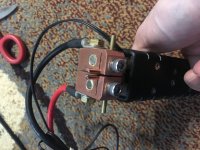
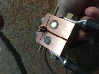
The picture of electrodes look like there is a nickel core, or some silvery-looking metal.
I recommend thick pure copper for the tips.
I recommend thick pure copper for the tips.
I'd say find or make a more powerful welding probe, and/or contact the seller. What are you welding with them? They should be suitable for 0.1mm nickel but not more, as they are quite thin.Schultz said:Hello guys,
I use a kwelder for a few years and recently bought for it a welding pen from aliexpress and some electrodes that come with the pen.
Now the problem is that the electrodes stick to the nickel strip after the welding and they even melted(this happened when I calibrated the system and pushed the electrodes into a chunk of copper).
I get 1400-1500a from my power source so don’t think this is a problem.
I cleaned everything with isopropyl alcohol but the result is still the same.
What should I try in this case?
With a more powerful probe do you mean a more powerful welding pen or only the electrodes or the entire combo??
I used it on 0.2mm nickel.
I was thinking to cut the thinner part of the electrodes and try to sharpen a bit the remaining part. If this doesn’t work I seen some 3mm C14500 tellurium copper rodes. Am I on the right track with these or some other materials are needed?
I intend to weld 0.3mm nickel strips or 0.2mm copper sandwiched with 0.1 nickel. With the original electrodes of the welder this is possible, I mean I already welded the above materials onto cylindrical cells.
I mean a welding pen that doesnt stick ormelt from the high power that kWeld provides.Schultz said:With a more powerful probe do you mean a more powerful welding pen or only the electrodes or the entire combo??
Would be worth a try. C14500 is known to melt later and stick less.Schultz said:If this doesn’t work I seen some 3mm C14500 tellurium copper rodes. Am I on the right track with these or some other materials are needed?
I think I solved it.
I managed to weld 0.15mm nickel sandwiched with 0.2mm copper.
Now it doesn’t stick anymore and the welds look good.
I ordered also some 3mm tellurium rods but at this point I don’t think they are needed but they could be good spares in the future.
A big thanks to all!
I managed to weld 0.15mm nickel sandwiched with 0.2mm copper.
Now it doesn’t stick anymore and the welds look good.
I ordered also some 3mm tellurium rods but at this point I don’t think they are needed but they could be good spares in the future.
A big thanks to all!
Attachments
yes it is, but I am quite busy with the new pro welder and also other projects for customers and therefore I am a bit slow in answering. And I also don't work over the weekendsSchultz said:@tatus1969 is your email working? I am trying to reply to an email from you since Saturday but without any luck.
") Cheers Frank
Cheers Frank
Oscillator Ocelot
100 µW
- Joined
- Dec 25, 2022
- Messages
- 9
Sorry for my delayed reply, holiday cheer kept me away from following up sooner.
@amberwolf
Thank you for such an informative reply! The possible scenarios you mentioned helped me better diagnose the battery, allowing me to confidently address the problem.
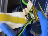
You were 100% correct about the interconnect between the cells failing. After I carefully removed the shrink wrap from the battery, I discovered a full disconnect hidden in one of the tab interconnect folds. I bridged the disconnect with alligator clips and brought the battery pack down to a safe storage voltage. Everything else looked undamaged to my novice eye.
Now I’m left with the dilemma of how to reconnect the tabs. They’re thick metal tabs (maybe around 0.15mm each tab). I don’t know how they can be reconnected without factory tools. Ugh.
Something else I noticed that confused me. The balance wires and power cables were soldered directly onto the battery tabs. I thought the high heat from soldering is supposed to be very destructive to the battery internals, hence the spot welding. Are lithium polymer cells more resilient to soldering heat than lithium ion cells?
@BVH
Thank you for sharing your experience! That helped me decide how to configure my replacement power source. I was leaning in the parallel dual 3S/6000 Graphene direction, so knowing that it works for you was what I needed to hear to go for it. What you mention about the 3S vs 4S current flow fits with what I suspected. It’s reassuring to know my understanding of the electrical properties behind these welds is advancing in the right direction. Now I just have to wait for the backordered batteries to be shipped.
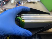
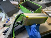
View of the lipo Graphene battery internals for the curious:
@amberwolf
Thank you for such an informative reply! The possible scenarios you mentioned helped me better diagnose the battery, allowing me to confidently address the problem.
You were 100% correct about the interconnect between the cells failing. After I carefully removed the shrink wrap from the battery, I discovered a full disconnect hidden in one of the tab interconnect folds. I bridged the disconnect with alligator clips and brought the battery pack down to a safe storage voltage. Everything else looked undamaged to my novice eye.
Now I’m left with the dilemma of how to reconnect the tabs. They’re thick metal tabs (maybe around 0.15mm each tab). I don’t know how they can be reconnected without factory tools. Ugh.
Something else I noticed that confused me. The balance wires and power cables were soldered directly onto the battery tabs. I thought the high heat from soldering is supposed to be very destructive to the battery internals, hence the spot welding. Are lithium polymer cells more resilient to soldering heat than lithium ion cells?
@BVH
Thank you for sharing your experience! That helped me decide how to configure my replacement power source. I was leaning in the parallel dual 3S/6000 Graphene direction, so knowing that it works for you was what I needed to hear to go for it. What you mention about the 3S vs 4S current flow fits with what I suspected. It’s reassuring to know my understanding of the electrical properties behind these welds is advancing in the right direction. Now I just have to wait for the backordered batteries to be shipped.
View of the lipo Graphene battery internals for the curious:
Attachments
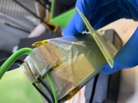
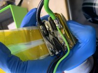
I don't see any other damage, either.Oscillator Ocelot said:You were 100% correct about the interconnect between the cells failing. After I carefully removed the shrink wrap from the battery, I discovered a full disconnect hidden in one of the tab interconnect folds. I bridged the disconnect with alligator clips and brought the battery pack down to a safe storage voltage. Everything else looked undamaged to my novice eye.
It looks more like a mechanical-force disconnect (as if something were placed between them and pulled outward along the axis of the pack, tearing the tabs apart) than a heat-induced one (from overcurrent/ poor connection/etc). Since the cells aren't swollen, I don't know what could cause that. (swollen cells have certainly done that kind of damage, but they don't unswell, so you'd see this). In this case, I see what looks like torn edges of the tabs, which only happens mechanically.
The tear actually sort of looks like it happened "lengthwise" across the tabs, as if the balance wire on it was pulled hard enough to stress the aluminum tab and start a tear. Then at some point the rest of tab tore thru, and the current path was broken. The wires from the pack don't appear to have any strain relief, so if that wire is shorter than the others even by a little bit, then there'd be more stress on it, potentially allowing this to happen.
A heat-induced disconnect normally leaves arc damage if it happened during a high current instance, or even actually vaporized edges, which I don't see, but would leave some sign of whatever melted from the heat to allow the disconnection. Since there doesn't appear to be any, it probably didn't fail during use.
Now I’m left with the dilemma of how to reconnect the tabs. They’re thick metal tabs (maybe around 0.15mm each tab). I don’t know how they can be reconnected without factory tools.
It looks like the tabs were crimped together, possibly with a current passed thru them during the crimping, which would weld them together. You may actually be able to do the same sort of thing using the Kweld, if you are getting new packs to power it from anyway. If you can use some form of clamping to secure the two tabs such that they overlap, then pass the welding current thru that clamp so it welds the two tabs together, along as much of the contact area as possible.
You may be able to solder them together, but it is likely one of the tabs on each cell is aluminum and the other tinned copper. There are some pretty old threads around here on soldering to A123 tabs, or other pouch tabs, including methods to minimize the heat getting into the cell pouch. I don't have any links ATM, but they're probably from a decade or more ago, especially from when the ebike racing thing was big.
Another possibility is to use some copper (or whatever) strip of appropriate thickness to create a connecting strip between the two tabs, and roll each end of it up with a tab, then crimp that roll as securely as possible, so you have as solid and low-resistance a connection as possible.
They may simply just ignore the potential problems this can cause, and they may be using a high-wattage iron with a very large heat-soaked chisel tip to quickly solder them onto the tabs. Pretinning the wires, and using appropriate flux to ensure fast bonding to the tab material, would minimize the time the heating of tabs occurs.Something else I noticed that confused me. The balance wires and power cables were soldered directly onto the battery tabs. I thought the high heat from soldering is supposed to be very destructive to the battery internals, hence the spot welding. Are lithium polymer cells more resilient to soldering heat than lithium ion cells?
There've been some discussions over the years about soldering tabs to pouch cells that cover various pluses and minuses and techniques.
Oscillator Ocelot
100 µW
- Joined
- Dec 25, 2022
- Messages
- 9
@amberwolf
Thank you for your additional insight! I didn’t know that some of the tabs are aluminum, and so are a challenge to solder. I think I’ll try spot welding them back together once my new batteries arrive (still back ordered, ugh). I’d definitely wonder if that would effectively reduce the battery packs total amp output, though. I guess I’m still deciding my approach on how to reconnect the now quite short tab to the other tab.
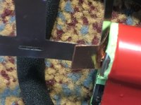
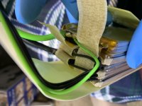
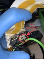
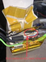
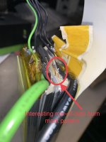
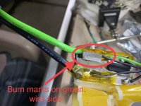
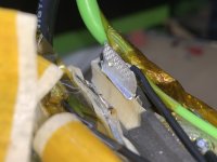
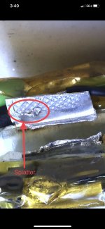
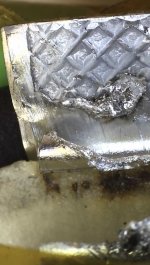
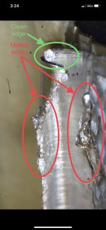
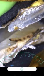
I performed a much closer inspection of the severed tab interconnect in an attempt to more definitively diagnose the cause of the disconnection since there seemed to be conflicting evidence. Closer inspection behind the tab folds revealed burn marks and melted edges. Although I agree that the lack of strain relief on the balance wires could be a problem, and may have contributed to the genesis of a traveling tab failure, it appears that excessive current overwhelmed the tab, melted it, and caused arcing.
Something interesting I noticed was the burn mark pattern. There appears to be a row of burn mark dots. I wonder if a new burn mark was created with each Kweld use, consuming a little more of the tab each time.
I used a special digital camera-microscope to try to photograph the burn marks and melted tab edges. The resolution is a bit low, but the damage is still visible.
I’m curious about your thoughts with this new evidence.
New evidence:
Thank you for your additional insight! I didn’t know that some of the tabs are aluminum, and so are a challenge to solder. I think I’ll try spot welding them back together once my new batteries arrive (still back ordered, ugh). I’d definitely wonder if that would effectively reduce the battery packs total amp output, though. I guess I’m still deciding my approach on how to reconnect the now quite short tab to the other tab.
I performed a much closer inspection of the severed tab interconnect in an attempt to more definitively diagnose the cause of the disconnection since there seemed to be conflicting evidence. Closer inspection behind the tab folds revealed burn marks and melted edges. Although I agree that the lack of strain relief on the balance wires could be a problem, and may have contributed to the genesis of a traveling tab failure, it appears that excessive current overwhelmed the tab, melted it, and caused arcing.
Something interesting I noticed was the burn mark pattern. There appears to be a row of burn mark dots. I wonder if a new burn mark was created with each Kweld use, consuming a little more of the tab each time.
I used a special digital camera-microscope to try to photograph the burn marks and melted tab edges. The resolution is a bit low, but the damage is still visible.
I’m curious about your thoughts with this new evidence.
New evidence:
Attachments
-
 102D5B72-20DD-4E4C-AE00-E7260D48ABCC.jpeg580.3 KB · Views: 345
 -
 18F16BC3-27B0-4E1E-96A6-FF95C85642E4.jpeg539.6 KB · Views: 344
 -
 D2EDEA58-DC25-475D-BB32-D0202ACA655B.jpeg530.9 KB · Views: 343
 -
 8FD45B82-6217-41A1-B827-0965749E3216.jpeg925.8 KB · Views: 343
 -
 0B5AEA5C-00DE-440D-ADAF-4195D20CB065.jpeg402.4 KB · Views: 344
 -
 A8061CA3-E73A-4F35-9D6A-7E09E2F29EF2.jpeg554.4 KB · Views: 345
 -
 E2B61C83-FFDD-4DDE-AA17-FBFFE20E7D0F.jpeg340.3 KB · Views: 345
 -
 58A9499C-B08D-4E31-88BF-F107260441EC.jpeg408.2 KB · Views: 346
Oscillator Ocelot said:I performed a much closer inspection of the severed tab interconnect in an attempt to more definitively diagnose the cause of the disconnection since there seemed to be conflicting evidence. Closer inspection behind the tab folds revealed burn marks and melted edges. Although I agree that the lack of strain relief on the balance wires could be a problem, and may have contributed to the genesis of a traveling tab failure, it appears that excessive current overwhelmed the tab, melted it, and caused arcing.
To me this looks like overcurrent as well as some damage during assembly. I'm not sure what the inrush current looks like from the kweld but it's looking like too much for how this pack was soldered. I expected better but to be fair this is also likely being used outside its normal design envelope.
What you labeled as splatter looks like melted aluminum to me. If you tig weld dirty aluminum it can look like this if the cleaning % isn't high enough, the shielding gas is weak / contaminated, or the metal / fill rod is dirty.
The row of dots might be the diamond pattern playing a role in conducting / insulating / not handling heat as well. It might also be thinner in the divot of the diamond and easier to melt there.
Oscillator Ocelot
100 µW
- Joined
- Dec 25, 2022
- Messages
- 9
Oh wow yah I bet you’re right about the Diamond pattern! That would explain the uniformity of burn marks. Nice observation!
Oscillator Ocelot
100 µW
- Joined
- Dec 25, 2022
- Messages
- 9
So I had a suspicion about that diamond pattern and how it relates to the tab welding process. It seemed to me that in order to achieve a spread out diamond pattern after an electrical resistance weld, an elaborate cascade of individual welds would be necessary to avoid using enormous current for a single weld instance. All of that seems way too impractical for a high output manufacturing setting.
Turns out those battery tabs weren’t spot welded, they were joined using a process called Ultrasonic Metal Welding (UMW). That diamond pattern is a result of the “sonotrode” clamping down onto the battery tabs against an “anvil,” at which point a vibration welds the tabs together. It’s a really cool alternative solution for joining metals, but unfortunately the equipment costs thousands of dollars.
@tatus1969
Maybe your next project after finalizing the Kweld Pro could be to design an affordable ultrasonic metal welder! Maybe you could call it the Uweld
Examples of ultrasonic metal weld:

Image Source

Image Source
Turns out those battery tabs weren’t spot welded, they were joined using a process called Ultrasonic Metal Welding (UMW). That diamond pattern is a result of the “sonotrode” clamping down onto the battery tabs against an “anvil,” at which point a vibration welds the tabs together. It’s a really cool alternative solution for joining metals, but unfortunately the equipment costs thousands of dollars.
@tatus1969
Maybe your next project after finalizing the Kweld Pro could be to design an affordable ultrasonic metal welder! Maybe you could call it the Uweld
Examples of ultrasonic metal weld:
Image Source
Image Source
Hillhater
100 TW
Spot, friction (UHM) , etc are all established proven methods…
..but laser welding seems to have become a commercial/ domestic viable option also.
It would be great if smeone developed a small scale laser tab welder..
[youtube]F3OBcc2mHVk[/youtube]
..but laser welding seems to have become a commercial/ domestic viable option also.
It would be great if smeone developed a small scale laser tab welder..
[youtube]F3OBcc2mHVk[/youtube]
Oscillator Ocelot
100 µW
- Joined
- Dec 25, 2022
- Messages
- 9
Oh man, imagine the antics that would ensue if a college fraternity got their hands on something like that
windtrader
1 kW
Appreciate all the useful information and experiments you've done. From your posts and many others over the hundreds, it seems the practical limit of the kWeld on Cu is .1mm with the Ni tape. Maybe .15 Cu plus Ni tape.ichiban said:Hope my shared info here help to clarify your questions re how to reliably weld 0.15mm Ni(Fe) + 0.2mm Cu or thicker using current model kWeld (upto 2022.10 version, mine was circa 2018). Be very careful when you mod something. Make sure you really know what you are doing / or ask questions here. Safety first. I tried to post pictures of my mods believing it helps you guys to see the details. Have fun and be safe !
Mods are needed if reliable .2mm Cu is to be accomplished, stock kWeld is not strong enough. There were so many mentions about .2mm Cu spot welds but they all require mods.

Oscillator Ocelot
100 µW
- Joined
- Dec 25, 2022
- Messages
- 9
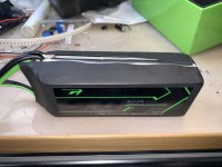
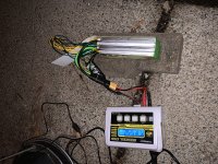
That large ARM processor makes me think you have some sophisticated capabilities planned for that beast of a welder
windtrader
1 kW
Won't the limiting factor still be power input capacity like the current model? I could weld .02mm copper if I add capacitor or maybe a stronger battery.
Part of that is that the unit will have a touch TFT, which requires lots of pins and power, but part of that is also lots of things to control. The unit has a built-in 4S ultracap charger with balancing and thermal monitoring, and lots of other process variables.Oscillator Ocelot said:That large ARM processor makes me think you have some sophisticated capabilities planned for that beast of a welder
Similar threads
- Replies
- 0
- Views
- 591
- Replies
- 8
- Views
- 910
- Replies
- 23
- Views
- 2,742
- Replies
- 1
- Views
- 603