Lebowski controller IC 2.B0 source code and (short) explanation

Added version 2B0. This one implements the 45 degree improvement suggestion.

The complete source code and hex (for easy programming when you have a pickit programmer) can be found in the first post of this thread. Changes are in file determine_update.s
 
Just like you said, i used 10K/3K3 divider on throttle line and added 470uF cap across 3K3.
I got 1s voltage rise to 3V3 and that is enough to reliably start compressor every time.
I will now use this with AC clutch signal. YAY!
 
arber333 said:
Just like you said, i used 10K/3K3 divider on throttle line and added 470uF cap across 3K3.
I got 1s voltage rise to 3V3 and that is enough to reliably start compressor every time.
I will now use this with AC clutch signal. YAY!

The caps is between the throttle input and ground ? With th 10k to ground and the 3k3 to the 5v ?
 
Lebowski said:
The caps is between the throttle input and ground ? With th 10k to ground and the 3k3 to the 5v ?

Of course not. 10k is inline and 3k3 is to GND. 470uf is from junction to GND. I apply 12v into this line and I get slowly rising 3v3 on throttle line.

However I will have to work on this still. Last time I kept pressure in hoses and tried to restart. Motor conked out. Maybe slower throttle ramp? I use 1.2,0,0 now.
 
Well, when i connected some wires to have offboard controls of reset and setup etc i saw some serious LED fiddling. Leds would come on at once or controler would just conck out if i tried to provide throttle.
It was giving me hell untill i decided to decouple all the pins where wires are involved. It seems at 360V+ EMI is rampant throughout the wiring. I have good GND connection to motor, but still i added 104 caps from each input to GND. At least for those that doesnt already have caps on. Now the LED blinking stopped.
I have good starts with acceleration limiter set broadly at 5 to 8. Also i set wiggle angle at 120deg and wiggle freq at 180Hz.
 
arber333 said:
It was giving me hell untill i decided to decouple all the pins where wires are involved. It seems at 360V+ EMI is rampant throughout the wiring. I have good GND connection to motor, but still i added 104 caps from each input to GND.
Are you using twisted-pair wiring? If not, you might want to do that.
 
amberwolf said:
Are you using twisted-pair wiring? If not, you might want to do that.

Twisted pair is used when you have differential signals or power supply. What i use are just 5V digital signals. Twisted wire wont work with same polarity signals.
But i succesfully decoupled noise from reset and setup lines with 104 caps directly or near the uC pins. I suggest to update schematic to include decoupling caps on every uC pin that accepts digital signals over wires. On throttle signals i put 102 cap.
Also i put 10K pulldown resistors on every pin that is not in use.
 
All (voltage) signals are differential, and almost all are with respect to ground. I would wire twist all signals with a ground wire. The ground twisted wire should be connected on both ends. If your resolver or hall signals are far away, also wire twist these.

An exception to most voltages beong ground refered is the high side gate signal, this one is refered to the source of the high side transistor.
 
Lebowski said:
I would wire twist all signals with a ground wire. The ground twisted wire should be connected on both ends.

I tried this also. I used GND wire and connected at both ends. No noticeable improvement. Only after caps inputs calmed down.
 
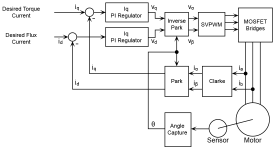
I think there is some confusion as to what the 45 degree rotation of the error signal looks like. I use it for both sensored and sensorless, but the example here is sensored:
foc_diagram.png
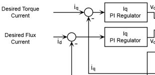
The picture above is the standard setup for sensored FOC you see everywhere. The bit I changed is in this section :
foc_orig.png

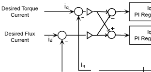
I changed it to
foc_diagram2.png
As you can see gain sections and a cross coupling has been added after determining the differences between wanted and measured I components. This difference signal is called the error signal. The blocks I added implement the 45 degree rotation of the error signals. It uses some constant gain (the triangles, gain = 1/srqt(2)) and the signals are added / subtracted from each other.
So the Iq (same for Id) requlator is updated using information from both the Iq and Id loop, in effect linking the loops together.

I have never seen this done like this before...

NOTE: this is a quick draft, the + and - might be interchanged. Also they are rotation direction dependent.
P.S. in version 2.A1 it did not rotate over a constant 45 degrees as shown here (the 45 degree comes from both gains being equal to 1/sqrt(2)) . In 2.A1 the gains were different from each other (also there were 4 instead of 2, one in each path going to the adders) and constantly re-calculated to give a rotation over the motor impedance angle (based on measured R, L and motor speed).
 
the block where you add/subtract Id & Iq, i have not seen that but its hard to say i have read so many thousands of papers each describing their own way of doing FOC. there are a lot of variations, usually with some trade off you gain this but sacrifice that. in military/commercial aircraft you're given a spec to meet and the document is if you printed it 8.5x11 would be an inch thick. in there is basically a requirement to PROVE analytically (and to lesser degree by test) that the controller is stable under all operating conditions. and for THAT reason (customer spec) you don't really see too opportunity to try something new and different because its hard to prove that new and different is also guaranteed to be stable under all operation conditions. so in the end.. you stick with what was simple and working and 20 years old.
 
To explain the 45 degree thing further, controlling real and imaginary current at the same time is basically a 2 dimensional control problem. To reach the steady state your updates need to 'walk' straight to the steady state point.

However, the information telling your in which direction to walk is the current. But your walking to the steady state is all done in voltage domain.

If frequency is low, the indicated direction (current) is the correct one, as at low freq only motor resistance plays a part. So in the voltage domain you walk straight to the correct operating point.

At high frequency (high motor erpm) the indicated direction is 90 degrees off from the direction you need to take, because of the 90 degree shift between current and voltage (as caused by motor inductance) . Instead of walking to the steady state in a direct line, you are now circling the steady state point, but never reaching it (never even get closer to it). This because you indicated direction to take is 90 degrees wrong.

So what you do is you take the direction indicated by the currents and you rotate it over a certain amount of degrees to get to the correct direction to take in the voltage domain. This rotation ideally is the phase rotation of the motor impedance. BUT if you don't know the rotation of the motor impedance, then 45 degree is always good. You may circle a little bit to get to the steady state point, but you will always get closer to it.
 
Hi Lebowski

I still consider starting torque with my motor rather lame. I have read on the characteristics of IPM motors. As you may know Leaf motor is 8 pole IPM motor.

I wanted to ask you if you considered IPM motors with your software? Here there are two torque components. One reactive and one resistive... well reluctant anyway. With FOC this results in changing d and q proportionally. At speed i cant see any fault in sensorless operation and it works really well. However like i said on start there is just not enough torque. Torque is really good after some 30km/h which is mode2 to mode3 transition.
Theory says reluctance torque component is more dominant with large amp loads then. Now I should be able to apply more amps to armature here, but system wont let me.

Would you consider adding a correction in your code just for IPM motors by shifting optimum angle of torque from 90deg to some 120deg? Or some selectable parameter from 90deg to 135deg of torque angle? This would just apply for speed of up to transition from mode 2 to 3 when the motor is struggling to take off. Maybe this would help with torque generation for Leaf motor on start. Would that be doable?

TNX
 
Sorry, I am not adding any new code. The whole reason for publishing the source code is that I dont need to continue with it. I broke down my hobby table where I did all my development, so cannot run any tests anymore. Its my home office table now...
 
arber333 said:
Hi Lebowski

I still consider starting torque with my motor rather lame. I have read on the characteristics of IPM motors. As you may know Leaf motor is 8 pole IPM motor.

I wanted to ask you if you considered IPM motors with your software? Here there are two torque components. One reactive and one resistive... well reluctant anyway. With FOC this results in changing d and q proportionally. At speed i cant see any fault in sensorless operation and it works really well. However like i said on start there is just not enough torque. Torque is really good after some 30km/h which is mode2 to mode3 transition.
Theory says reluctance torque component is more dominant with large amp loads then. Now I should be able to apply more amps to armature here, but system wont let me.

Would you consider adding a correction in your code just for IPM motors by shifting optimum angle of torque from 90deg to some 120deg? Or some selectable parameter from 90deg to 135deg of torque angle? This would just apply for speed of up to transition from mode 2 to 3 when the motor is struggling to take off. Maybe this would help with torque generation for Leaf motor on start. Would that be doable?

TNX

Mine had amazing torque from 0-100km/h At any speed in that range I could fry tires. 0- ~70km/h on the track with slicks I could still fry tires.
 
So what did you use to get better response? Did you just lower winding resistance and add more phase torque?
Or did you advance RLS encoder signal? By how much? I tried up to 35deg and there wasnt any improvement. Do i have to use real degrees? That would be 4x35deg = 140deg electrical?

Now everything is great down to about 1500erpm. Whenever i apply throttle from stop motor jumps forward and then back with a kind of rattle. For a moment there is a weak pull forward with several shakes back and forth and then when motor is actually turning it suddenly pulls out and all is good.

I tried to calibrate RLS encoder to 1/10th deg - i still have confidence of only 6 on all points
Lower transition 2, 3 up to 400erpm to 1800erpm
I lowered FWD/REV change point as low as i am comfortable... 300erpm
I increaased phase output to 600A
I tried running with encoder assist and without.... no real difference on roll off
I tried with auto calibration of current sensors at 10A... not really sure if it makes any differnce
I set motor inductance at 120uH (measured is 180uH) and motor resistance at 48mR (measured is 180mR). The R setting seems to make the most difference with power available here.

After initial experiments with control loops in menu G i went back to autosetting. Should i be playing here?

tnx

A
 
arber333 said:
So what did you use to get better response? Did you just lower winding resistance and add more phase torque?
Or did you advance RLS encoder signal? By how much? I tried up to 35deg and there wasnt any improvement. Do i have to use real degrees? That would be 4x35deg = 140deg electrical?

Now everything is great down to about 1500erpm. Whenever i apply throttle from stop motor jumps forward and then back with a kind of rattle. For a moment there is a weak pull forward with several shakes back and forth and then when motor is actually turning it suddenly pulls out and all is good.

I tried to calibrate RLS encoder to 1/10th deg - i still have confidence of only 6 on all points
Lower transition 2, 3 up to 400erpm to 1800erpm
I lowered FWD/REV change point as low as i am comfortable... 300erpm
I increaased phase output to 600A
I tried running with encoder assist and without.... no real difference on roll off
I tried with auto calibration of current sensors at 10A... not really sure if it makes any differnce
I set motor inductance at 120uH (measured is 180uH) and motor resistance at 48mR (measured is 180mR). The R setting seems to make the most difference with power available here.

After initial experiments with control loops in menu G i went back to autosetting. Should i be playing here?

tnx

A

One huge win I had was a resistor in series with the gnd of the rls encoder
You will have to dig though my posts to find it.
 
Arlo1 said:
One huge win I had was a resistor in series with the gnd of the rls encoder
You will have to dig though my posts to find it.

I found your post back from 2017.
So after all that I realized what made it super awesome and buttery smooth... The ground wire was breaking and as it got weaker it gained resistance this resistance between the ground and the encoder helps make a filter... SO I pulled it back into the shop to excited to sleep at midnight and added a 15 ohm resistor in series between the negative and the encoder and BAM its perfect. Its now 100% OWM quality for starts!!!

Please clarify for non native speakers here... :wink:
Did you add 15R resistor inline on the NEGATIVE power supply line (-) of the RLS encoder OR the GND SHIELD of the encoder signal lines?

Anyway I have my shield connected on single side to casing of the inverter. Both inverter and motor are connected to each other and car chassis via 6mm2 ground straps. I thought that would be enough...

tnx

Arber
 
arber333 said:
I found your post back from 2017.


Anyway I have my shield connected on single side to casing of the inverter. Both inverter and motor are connected to each other and car chassis via 6mm2 ground straps. I thought that would be enough...

tnx

Arber

I hope you meen the inverter enclosure and not the traction pack negative?

YOU NEVER connect either side of the main battery (Traction pack) to the chassis!
 
Arlo1 said:
I hope you meen the inverter enclosure and not the traction pack negative?

YOU NEVER connect either side of the main battery (Traction pack) to the chassis!

Yes yes of course. I ground motor, inverter and just about anything i added into the car by 6mm2 straps. Power cables are rubber coated welding core routed inside plastic water hoses for double isolation. That way there is more than 800Mohm between chassis and HV battery poles.
 
Arlo1 said:
One huge win I had was a resistor in series with the gnd of the rls encoder
You will have to dig though my posts to find it.

Well i have tried first with one 10R resistor inline on the RLS sensor supply line GND and i must report there was even more motor bucking on start. I actually dont have 15R resistor, but i remembered i have some inline chokes. If i used a choke as L and add a 100nF cap across 5V and GND i would get a makeshift LC circuit. That would probably help eating the pulses. Worth a try?

Do you have a decoupling cap across your RLS encoder power supply in addition to 15R? Inverter side of course?

tnx
 
I also spent a lot of time setting the gap and making sure the RLS chip was centered.
 
Arlo1 said:
I also spent a lot of time setting the gap and making sure the RLS chip was centered.

My RLS chip is centered into the same position the original resolver. I use the copy of resolver mount and i have CAD made center step for the RLS plate. That should be flawless. The vertical gap however could be a problem. I set it up with a caliper :).
I will go and check that tnx.

A
 
Lebowski? If i may...

Last weekend i was playing with recovery menu K.
I increased option h) Pulse width from 150us that Arlo declared to about 165us. Values at about 125 or lower would cause motor to surge on startup and on transition through throttle 0.
Also some values caused really annoying transients within car 12V which made the dials move on its own...

I changed option l) try restart for... from 500ms to 250ms which lessened the repeated little surges on start from still.

Also i changed option g) pulse when current drops below from autocomplete value of 25A to a value of about 12A. I noticed that with lesser value those starting surges went to almost none if i used this. But if i used as low as 10A pulsing with 550A phase current inverter wouldnt work.

However at the end of the day i was merrily driving on the highway at 130km/h and motor quit from sync. No big deal, i would just cut speed down to 75km/h so motor would resync. But this time that wouldnt work and i had to pull over and stop on the side and only then it would resync. This happened several times and i could feel the ticks when inverter tried to resync in middrive.

Bas, can you tell me some on how recovery works? Why do i need pulsing and how much? I would like to know because setting correct parameters really improved the takeoff experience. But i obviously sacrificed recovery capability...

tnx
 
Well i kept trying and eventually i figured out how the k) menu works.

First i played with option h) pulse width. I found out best for my system was 165
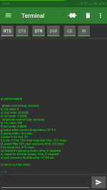
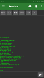
Then i tried to change the b) and c) filters. Together with lowering i) and raising time for the pulse l) i managed to bring the recovery up to 110km/h. Now it is much safer if motor goes out of sync on highway. I can safely lower the speed to 110km/h and motor recovers every time. My settings are in the screenshot.

I managed to get an OTG USB cable and connected serial gizmo to my phone. Together with Android terminal app it is easier than ever to tune up my car.

Next emboldened i went on to menu g) and tried to change parameters for drive 2. I noticed with recovery if i lower the gains function gets sharper but also smoother. So i changed option e) to 150 and instantly i got better start... not a whole better, but i could tell it made a difference. So i went and lowered the f) option to 10 and then to 5.

I also noticed in menu h) there is a b) filter option for drive 2. I tried to increase it to dampen the vibrations and it did help. I have it set to 220.
 

Attachments

  • Screenshot_2021-02-27-14-32-28-971_de.kai_morich.serial_usb_terminal.png
    Screenshot_2021-02-27-14-32-28-971_de.kai_morich.serial_usb_terminal.png
    125.8 KB · Views: 1,237
  • Screenshot_2021-02-27-14-32-00-214_de.kai_morich.serial_usb_terminal.png
    Screenshot_2021-02-27-14-32-00-214_de.kai_morich.serial_usb_terminal.png
    123.7 KB · Views: 1,237
Back
Top