My 40mph commuter Goped build thread.

MrDude_1 said:
Eventually I'll replace the entire frame, with the pan being structural. at that point it will be a nice stiff 3d structure, instead of a spine tube with a pan on top. But I consider that a second project.

As for the 80mm motor being overkill, I disagree. There are a couple things here.
First of all, I am NOT building a "golf cart EV"... Think less eco-car and more Tesla P85D. The idea isnt what will just meet a performance goal. Remember I am someone that took a 200hp, 400lb vehicle and commuted with it for half a decade. I have respect for high performance vehicles, but if the limitation of acceleration is power, and not the center of gravity (aka wheelie) or traction, It needs more power. :mrgreen: .


that DannyBoy scooter is probably what ur looking for.

u might be interested in this guy's build,
wont fit in ur trunk though... 8)
http://endless-sphere.com/forums/viewtopic.php?f=2&t=32903&start=100#p626501
 
sk8norcal said:
that DannyBoy scooter is probably what ur looking for.

u might be interested in this guy's build,
wont fit in ur trunk though... 8)
http://endless-sphere.com/forums/viewtopic.php?f=2&t=32903&start=100#p626501

lol, yeah, I remember reading this as he was doing it... I want to wheelie by him. :mrgreen:
 
Very nice! Would love to see some video's of that thing in action when you get it running.

And yes it is the part that connects the handlebar tube that gets loose. Happened to me once. You don't notice it is loose when you are riding until one day you will feel something jerk a bit when you hit the brakes which is the entire front wheel moving from it being so loose. With the clamp you are using you will notice if it is getting worse if the handle bars are raising, take a look at the part and you will see it will be raised up a bit from the frame and the locking part is poking out a bit, that is when it is time to take the handle bars off and retighten it. Funny story when mine fell off, I was trying to go as slow as possible to make it home but got stranded 10 miles from home. The entire handle bar fell out. I found a huge rock, put the part back in the frame hole and pounded down on the handle bar assembly with it, got home riding it at full speed!
 
minor update.... Motor is here! :shock:
I also designed a blinding backpack light, and wrote the code for it on a PIC, and will be putting the circuit together sometime tonight.. atleats I was, but now that the motor is here unexpectedly early, I may skip ahead a bit to that. :lol: :mrgreen:
 
So no massive update yet. I put the halls in the stator, but havent finished putting the motor back together yet to test.
I did just put this together at work... Anyone see any issues with these settings? If not, I plan to flash the controller up tonight, and maybe test the motor.

Controller-settings.jpg
 
well.. one thing was off.. low voltage threshold should be 59.2v... (3.7*16=59.2v)
I'll reflash to make that correct... but that aside....

It worked first try! I couldnt believe it, but the motor was spinning backwards perfectly.
I shifted the hall sensors wires around, and it went forward. :mrgreen: creeps with minimal throttle... spins up with throttle moved fast or slow..

so it works. I may have a false hall combo... or some other issue, but as of right now I am calling it good. Its 12:30am here right now. I spent the last few hours re-assembling the motor, getting it setup, making a mount so i could hold...etc.
I am just amazed the whole thing spins at all.

Next steps are to mount the motor, then controller... then batteries. Oh, and I never made a wood spacer, I made a new foam one, and as soon as I get more 206 hardener, I'll re-laminate it with West System epoxy.

Should be a fun time.
 
You can get a better than stock tab here: http://www.billetboard.com/showthread.php/8676-FS-Maddog-Front-Rear-Brake-Tabs-and-Frame-Fillers


I'm actually working on the scooter right now. Just taking a break and charging up all the batteries. Have to have them all the same before I parallel them.
 
OK... update time! :mrgreen:

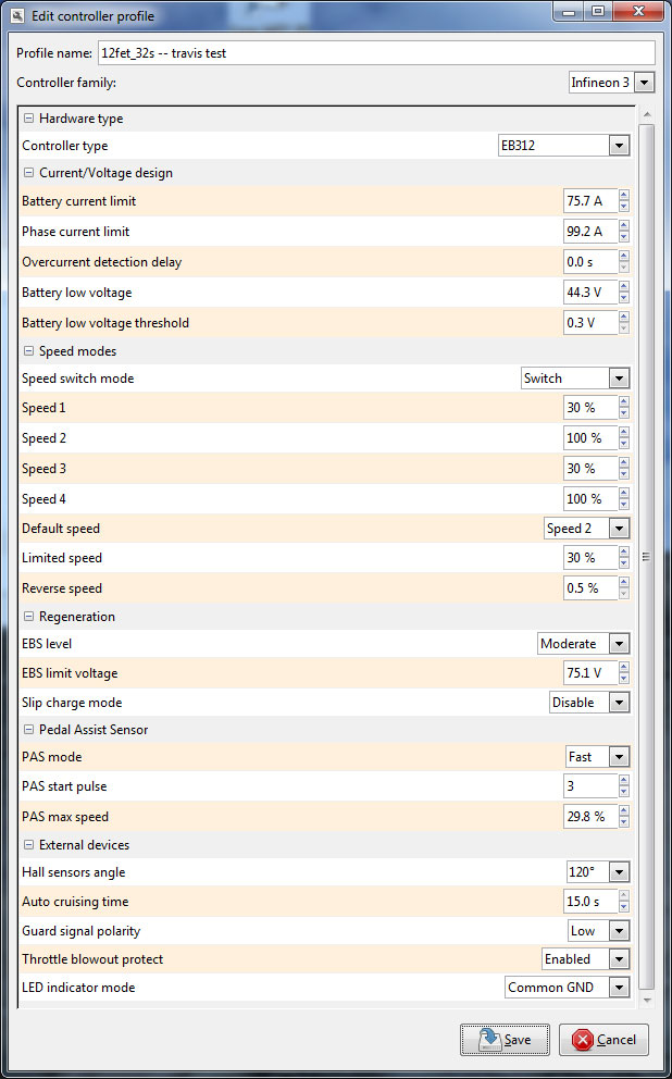
so first thing I did from the post above, was test out the motor and find my hall combos:
20150401_001147.jpg

20150401_001148.jpg


once I had that setup, I knew my motor controller worked with my motor and halls..
I still have a little to-do here.. The wires for the halls inside the motor kept moving into the way of the can bearing. so I used some superglue to tack them in place.. I need to re-open the motor and use the proper high temp silicone adhesive to hold them in place. I also found that the can of the motor is slipping on the shaft. I need to pin that down for sure. I'll get back to this later.

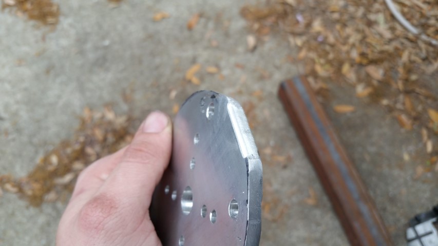
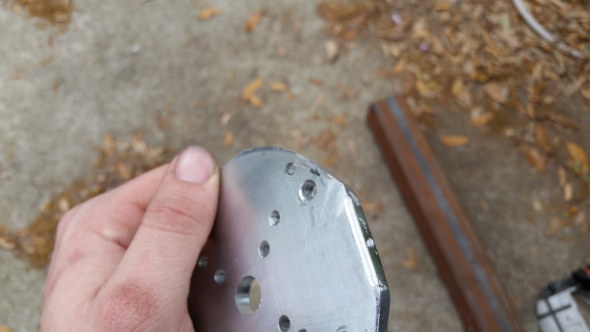
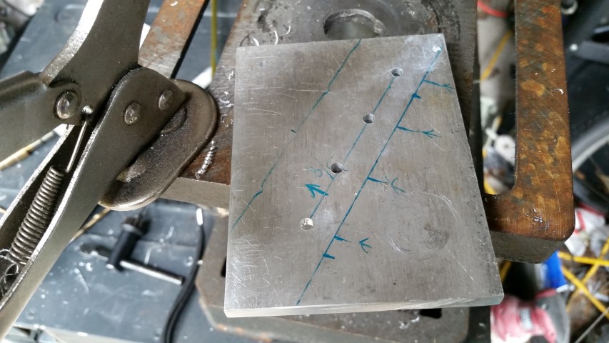
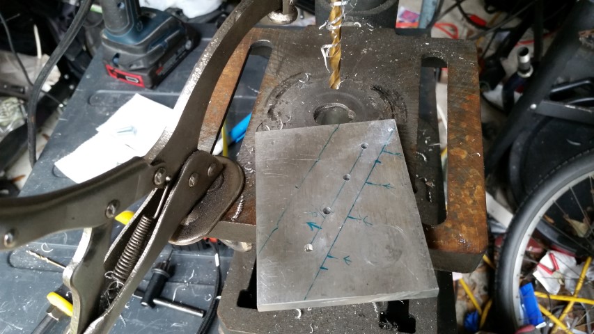
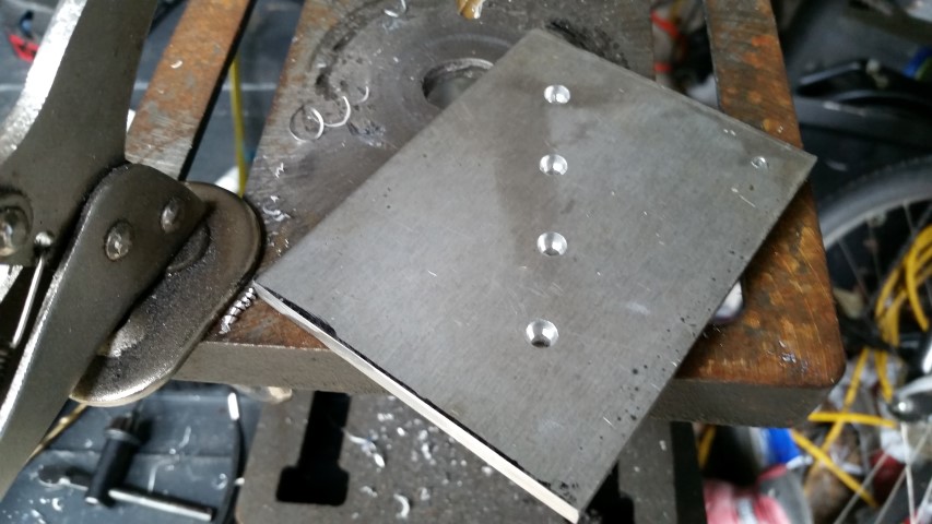
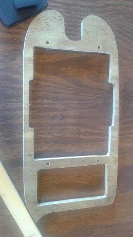
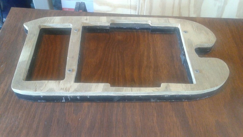
I dragged out my tabletop drill press and made the holes for the plate you see above... I then measured out and drilled the holes to mount the motor to the can. I decided to do a 3 bolt mount. I wish I took more pics, but I was working on it and didnt think about it at first. How I did it was simple..

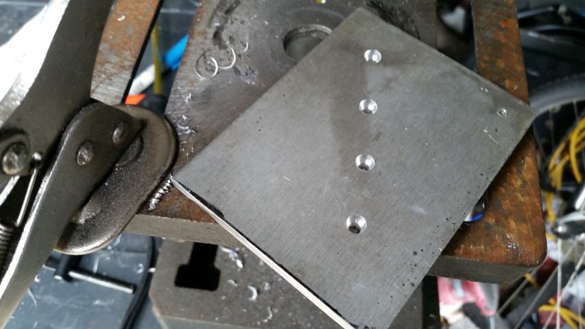
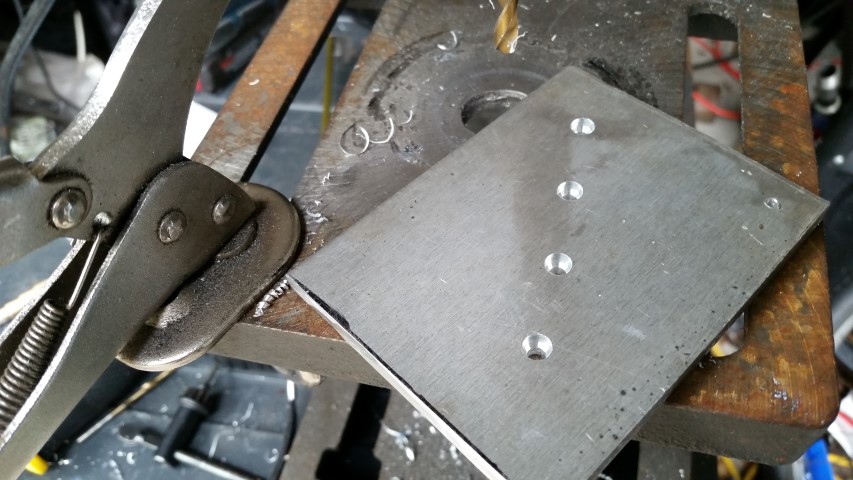
After figuring out where the bolt holes needed to be, I drilled them out.
I took the proper size nuts, and "spun" them on the belt sander.. this takes the cad plating off the side of the nuts, exposing clean metal for welding and makes them nice and round.
I then tightened the nuts to the plate.
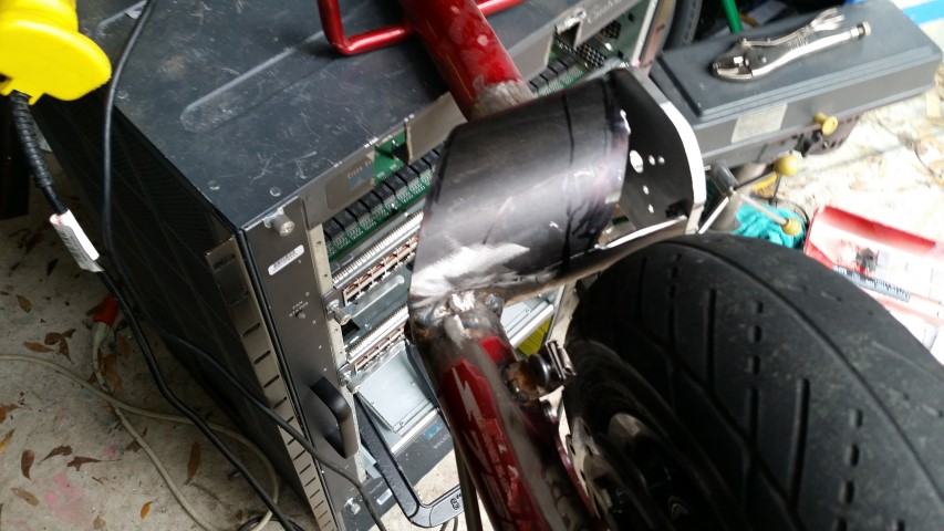
I put the plate up in place.. the nuts are now touching the frame tube. with a little filing,everything just clears with a very light, by hand press fit.
At this point I mark out the tube where I want to cut and keep.
where the cut marks meet, I drill holes, so they have curves in the corners instead of sharp points.
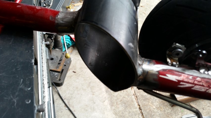
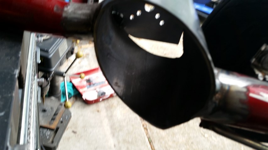
I chop the extra metal out of the tube... the top motor side cut is a little strange, but it had to match the fender/chaincover I will be using. all the other cuts are uncovered, so they are nice and straight.
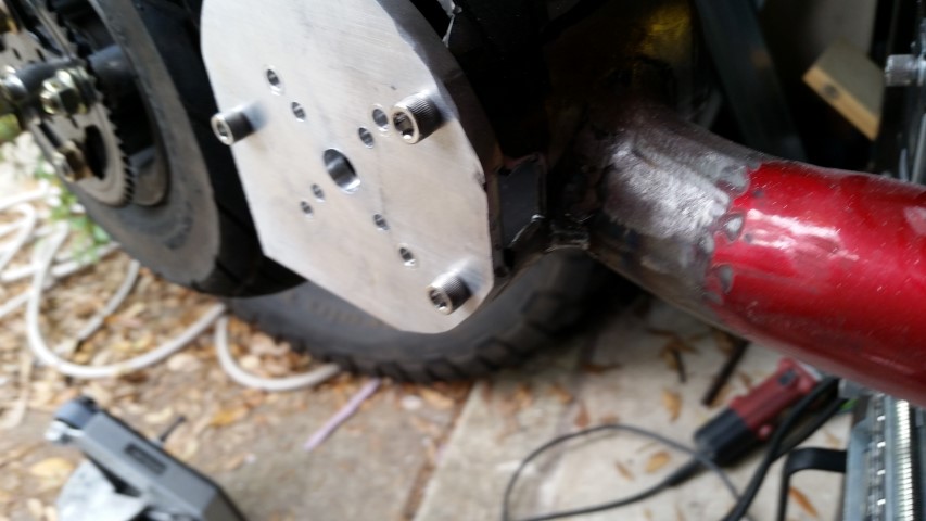
With the tube cut, theres access to see where the nuts meet the tube. tack the nuts to the tube, and unscrew the plate.
finish up the weld around them and you're good.
Then go back and clearance the inside of the nuts to clear the motor if needed.. i only needed a couple swipes of the file in one spot and it all cleared nicely.
I then took the mount plate, and used the belt sander a bit to make sure there were no sharp edges near where the wires were...
then bolt the whole thing back together, and use a little flap wheel so the edges of the plate match the tube.
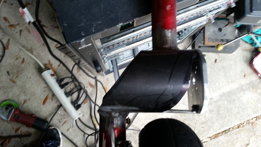
The lower rear corner was left alone, as it will eventually have my chain slack device there.
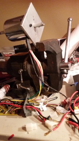
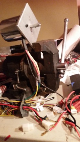
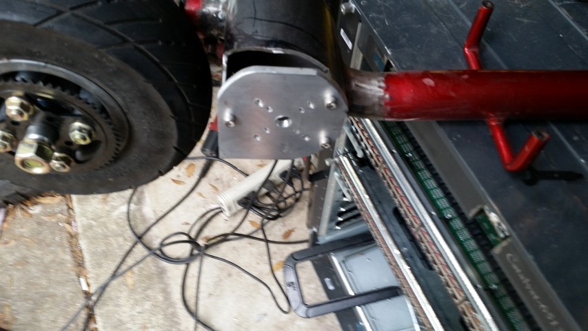
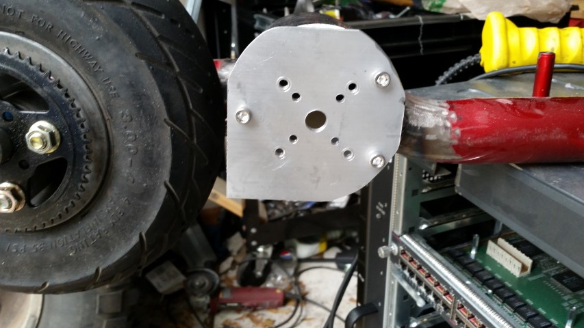
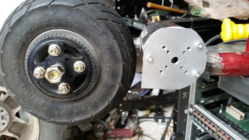
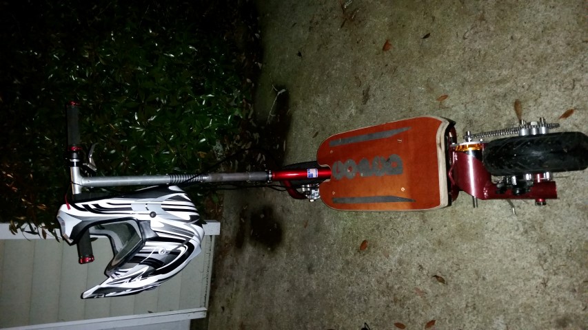
Pics of the mount:

20150404_101919.jpg

20150404_101921.jpg

20150404_102019.jpg

20150404_102022.jpg

20150404_102024.jpg

20150404_102028.jpg

20150404_102056.jpg

20150404_102058.jpg

20150404_102102.jpg

20150404_102104.jpg


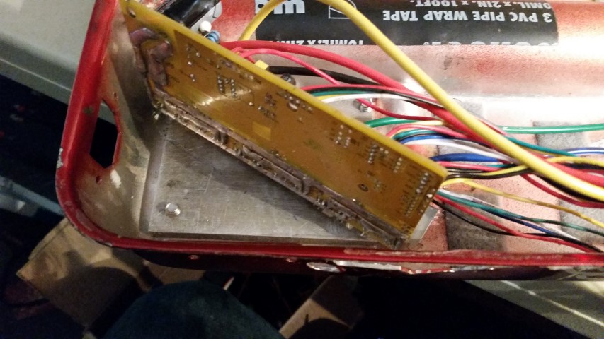
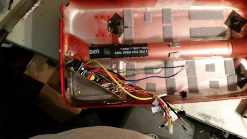
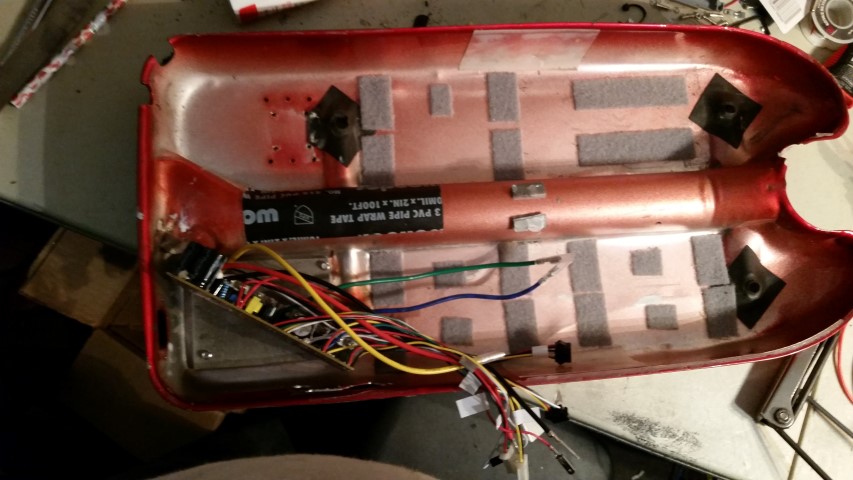
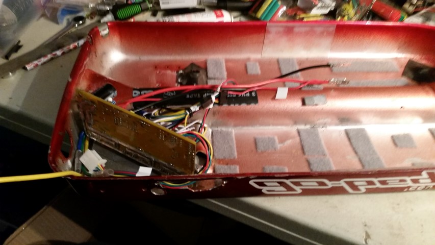
ok, with that done, I went on to the controller mounting.
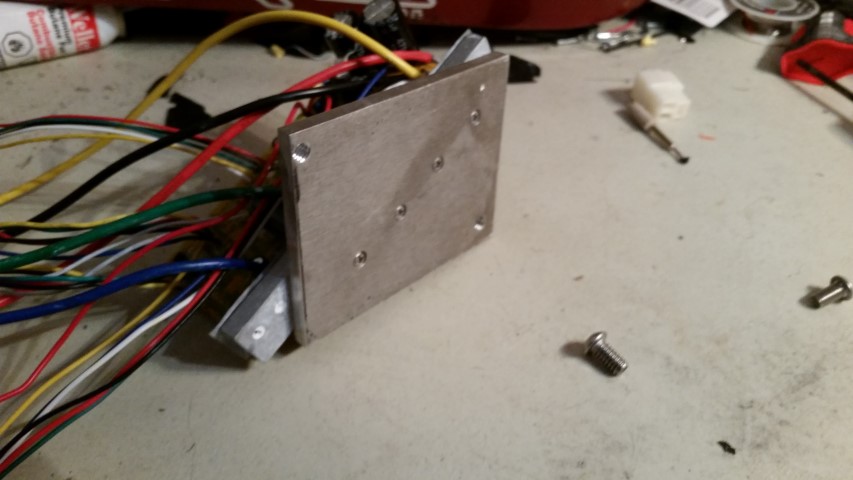
I marked out where my holes needed to be.
20150404_111644.jpg

20150404_111646.jpg


Then I flipped it over, and countersunk the heads
20150404_111651.jpg

20150404_111653.jpg

20150404_111654.jpg


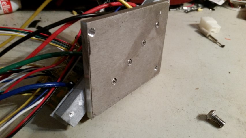
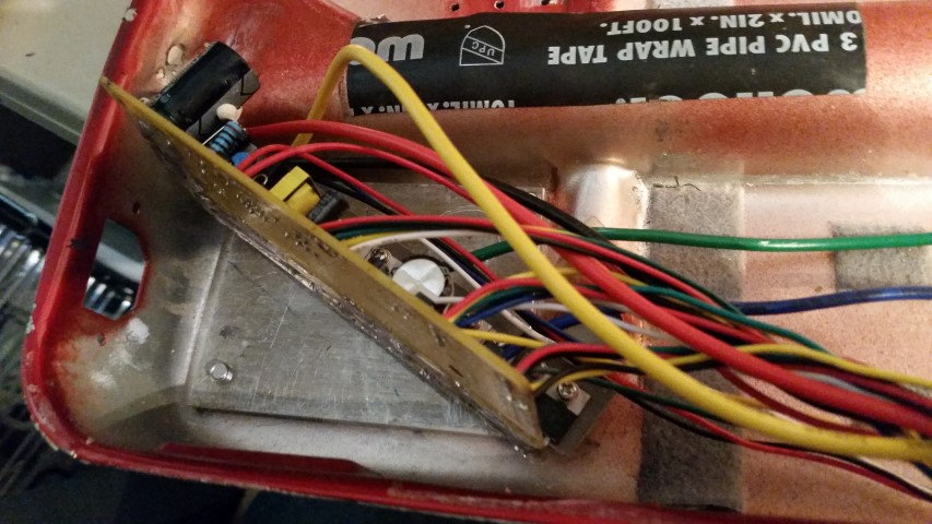
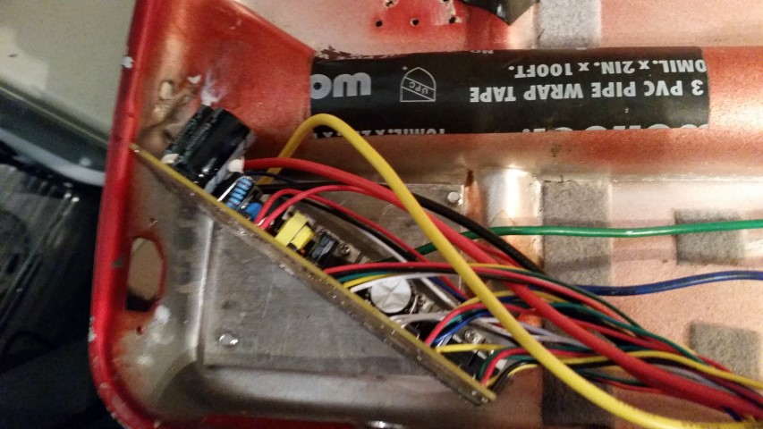
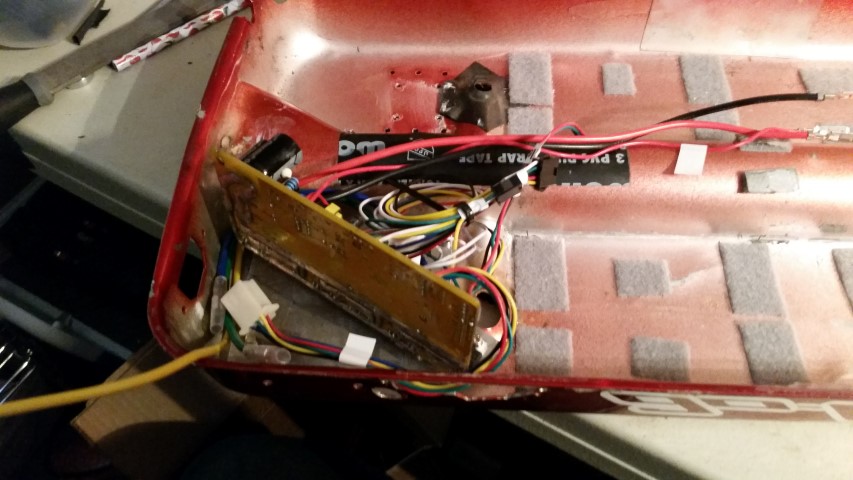
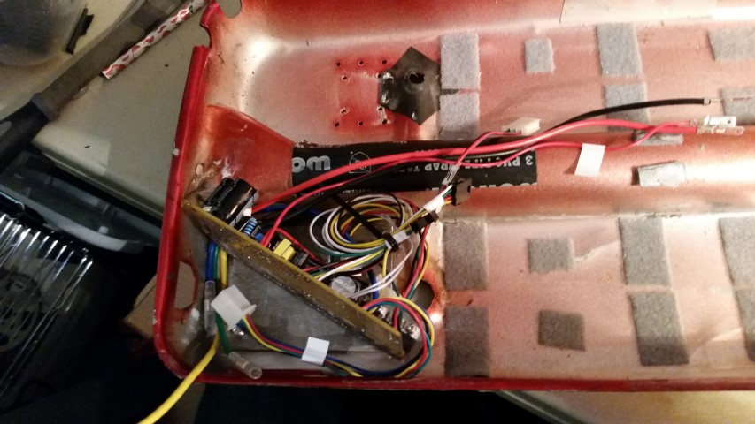
I then tapped the mounting holes for the plate... and installed the controller to it:
20150404_133536.jpg

20150404_133540.jpg


And then I screwed the plate to the pan with button head screws... all this will have heatsink paste on it when its on final assembly
20150404_134413.jpg

20150404_134415.jpg

20150404_134417.jpg

20150404_134420.jpg

20150404_134424.jpg

20150404_134426.jpg

20150404_134919.jpg

20150404_134921.jpg

20150404_134924.jpg


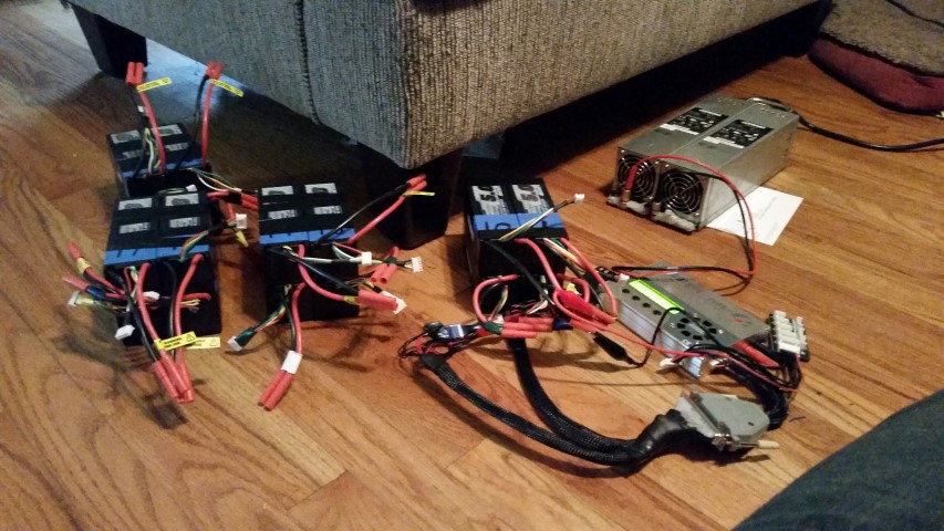
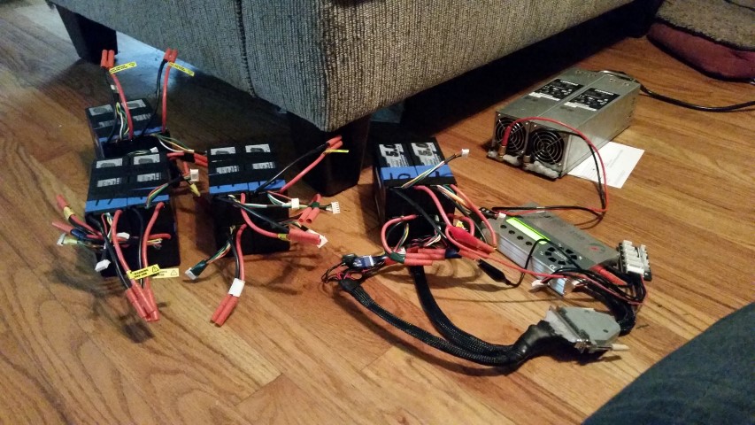
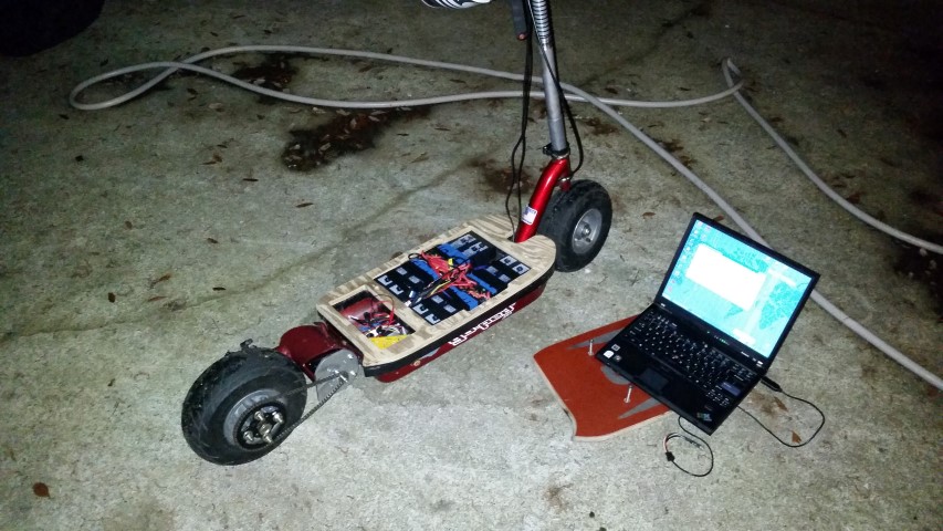
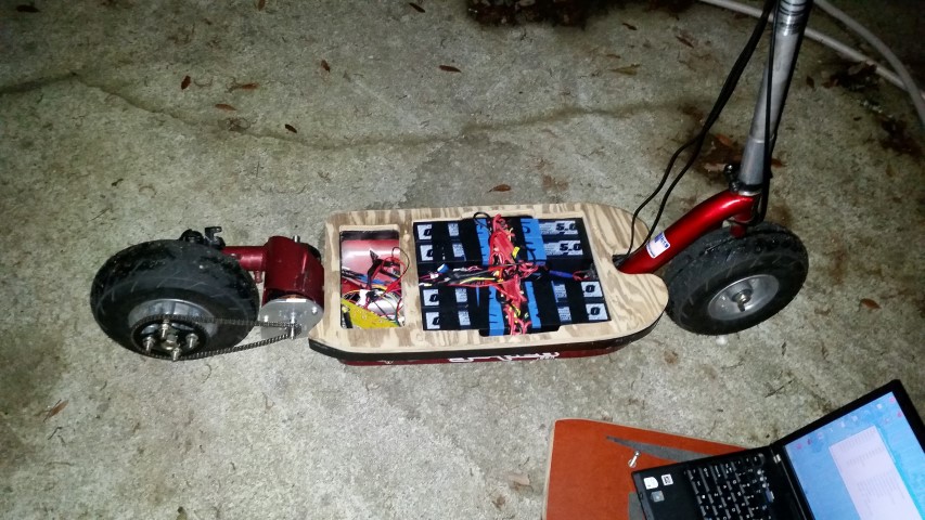
so last but not least... I charged up all 4 16s packs... 8 cells at a time. that way they could all be the same voltage when I paralleled them.
In these pics, we have two server powers supplies connected for 24 volts (24v @ 32 amp capable nice supplies.)
They're powering a 208b i charger.. where its charging each 5Ah 8s pair at a solid 1c rate of 5 amps.

for those wondering about lipo safety.. notice my jeans/leg in the corner. I am sitting next to this the entire time as it charges.... tv is on, but I am reminded... server power supply fans are LOUD!
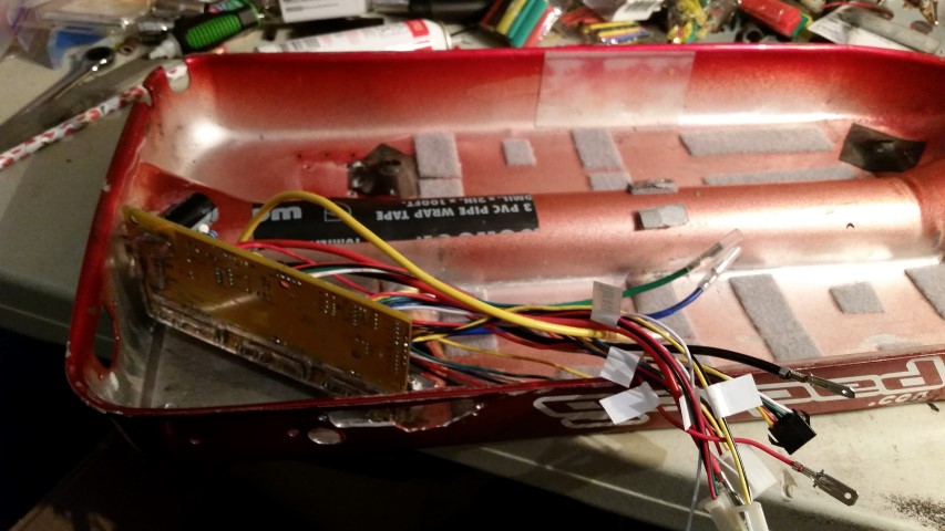
While this is charging, I made the balance charger harness ending in two 8s connectors and the main power harness.

20150404_144036.jpg

20150404_144040.jpg


so heres where I am at now...I need to:

1. finish the main power harness
2. change connectors on the controller.
3. add connectors to the motor.
4. tighten motor bell and secure internal wires in motor.
5. dry assemble everything... including the sprocket. It may need to be pinned on the shaft.

I think I can test ride it at this point.... but still have lots to do. have to weld the hook so I can fold it. I have to do the charger, the backpack lights, clean up all the welds for powdercoat, have it powdercoated, get a bothy fork, etc... oh and I probably will add a cycle analyst, so I need to get one of them and wire that in too... just lots and lots to do. getting there, slowly.
 
so it took a proper endmill, but I finally made the hole for the sprocket to screw and pin itself into the shaft. :D
as a happy coincidence, my new chain that I thought would be too short, actually fits exactly between the wheel and motor sprockets.... Im skipping the tensioner for this to work, but its nice for testing until I measure and get a new chain.
With everything almost finished, I measured for exactly the sprocket/wheel spacers I needed, and should have them knocked out by friday. waiting on material.
I flush mounted the motor mount bolts, and plan to put a heatsink on the mount plate, just a little extra cooling.

I havent made a new deck spacer yet, so I will be going to see my woodworking friend at lunchtime. We should be able to knock out the spacer pretty easily/quickly.


Not much left to do.. just test it out, and then tear it all apart again to cleanup, powdercoat, anodize and paint.... then all back together with some nice thermal compound between everything to keep it cool.
 
So much awesome going on in this thread! Subscribed.

I want a GoPed now :)

Nice BRZ btw!!
 
cal3thousand said:
So much awesome going on in this thread! Subscribed.

I want a GoPed now :)

Nice BRZ btw!!

Thanks... I had to look back to see when I had the BRZ in the pics.. lol.
Its a 2015 BRZ Series Blue... Other than the blue leather on the steering wheel, I love that car. :mrgreen: It will also get more power eventually... and just as overkill as this goped. :twisted:
 
Ive wanted to pull the race motor off my GoPed sport and electrify it, but Your making me think air tire is a must!
Looks good cant wait to see her running.
 
well.. not to say too much yet, but I have the scooter together enough to ride, except for the deck spacer and air in the rear tire.

I have revved it and messed with it a couple times on the stand now. I believe I have built something completely terrifying. :mrgreen:

I cant wait to try it out.
 
silviasol said:
Careful with the chain. I read a post once of a chain breaking apart from all the power of these motors and it cut his leg real bad.
oh yeah...I know. Ive seen dirtbike chains break too..
I am actually hacking up the stock fender/chainguard to work so I have a rear fender, and a proper chainguard that will still work later with a wider chain. I dont plan on keeping the #25 on there forever, just keeping it until I work out the sprocket ratio I need.
 
OK... so I have some issues to work out.

Yesterday my friend texts me and tells me the deck spacer is done... awesome. Its the only thing I was waiting on. After work I run over to his house (a good 2 hour round trip) and pick it up.
Looks good. Much better than I would have gotten from wood... you can ignore the gray on the black bottom plastic, thats just the tape gunk from when I was messing with it
2015041495132037.jpg

2015041495132626.jpg


With spacer in hand I was ready to try it all out... but I had to run back to work. ugh. theres always something. lol.
So I get home late and decide I will try it out.. just a little bit. I carry it downstairs, set it down and remember... I had to let all the air out of the rear tire to disassemble the wheel, so I could add my sprocket spacers. I normally filled the tire using the air compressor, but I JUST loaned that out to a friend who has a garage he can properly set it up in... So I try using my bicycle air pump... but unlike my air chuck, the pump is a 90* connector, and that wont fit behind the disc brake adapter. Frustrated, I raid bat-pig for quarters.
bat-pig.jpg

( Not my actual bat-pig, file photo used. Actual bat-pig located in man-lair, below TV.. Hidden from wife.)

Quarters in hand, I run over to the gas station and pump up the tire. While I am gone, the cat manages to steal and bat the wheel spacer around the house. So I trace that down too.. I find 3 quarters in the process, so thats 75% off what I just paid for air. yay.

So now its late. I take the scooter outside, and point it down the driveway. *click* button on.. all should be good. ease the throttle down.... oh yeah gotta connect the battery. duh.
pop the deck off, connect precharge, connect battery.. and we're good. deck goes back on.
i click on the the power, and ease the throttle down.... *JERK* the damn thing attempts to rip away. Now, not to brag, but I am good with motorcycles. You can give my the meanest, touchiest monster 2stroke you want, and I will ride it with a stupid grin on my face.
I did not have a grin on my face. I know the difference between a voltage throttle (what I have) and a current/torque throttle (what motorcycles have). I still didnt expect it to be THIS touchy.
I realize I am being stupid, so I go back inside and grab the brand new helmet I bought specifically for this thing...
I attempt to feather throttle away, but the slightest throttle and it jerk/ripped away. completely unrideable... But I DID start out with 75 battery amps and 100 phase amps.
So I drag out the laptop and reprogram it with 50 battery amps and 75phase amps.
I manage to get to the end of the driveway, but only with bumping the throttle. its really jerky.
I program it again, this time 50A battery, 50A phase and 50% throttle...
It will now move, but it "stutters". Its really jerky like the motor loses sync. Its not smooth at all, like it is when freewheeling.
I go around infront of my house once, but I realize all this is silly, so I pack it in for the night.
I need to get a cycle analyst.. I would try to build the current throttle arduino someone posted, but I also want a battery monitor, speedo, watt meter and all the other cool features it has... so might as well just get that.

But before I spend more money, I really need to figure out why the motor was "stuttering" like that.... too much current that it overwhelmed the cutoff? poor hall sensor placement? bad hall sensor? I have no idea. I need to look into it further for sure.. maybe at lunchtime today, if the weather cooperates.

I realize I stopped taking a ton of pics, but I havent been able to really get into working on it like I did at the beginning.. not for lack of desire, but when you get 10mins here, 15mins there... its hard to remember to take pics.
So heres some pics of it in my driveway lastnight. I sprayed some TEMPORARY paint on the raw steel to prevent rust.. and clearly it doesnt have the fender/chainguard I am working on... and the deck spacer needs to be sealed/painted... but here she is...
20150414_231747.jpg

20150414_231753.jpg

20150414_231805.jpg

20150414_231811.jpg

20150414_231835.jpg

20150414_231931.jpg

20150414_231939.jpg
 
another thought.. I really need to disable the regen right now.. between the chain slack whipping back and forth, and the small wheel for the regen amount, I should disable it.. it should smooth it out some when I am bumping the throttle....
 
What did you set the 'block time' at?

I would put it at .1

If it is set at 1 second, that could be your problem.
 
cal3thousand said:
What did you set the 'block time' at?

I would put it at .1

If it is set at 1 second, that could be your problem.

I believe "Block time" is the same as "Overcurrent detection delay"... its set at zero as recommended by Thud.

I am using XPD to program it, as Lyens controller software is not as flexible... but they both work identically as far as the controller is concerned.

Should I keep it at zero, or bump it up to .1?? I think Zero means off, and .1 means its still on a little...
 
as a side note, I really wish there was some kind of electronic hall timing adjuster on here... for fine tuning and such.
 
Disconnected the regeneration wire. Flashed it for 50a/50a/100% throttle. Works great. I just did a quick run down the street because it started to rain... but I can tell it's going to be gooood.
 
Back
Top