New "TSDZ2 Torque Sensor Central Motor"

Hello everyone.

Does anyone know if it is problematic to set a 48v motor to run at a 36v Akku using the OpenSource firmeware? Does this affect the cadence and/or the efficiency of the motor?

Or does that possibly even have advantages because the 48v moter is a little more current-proof and I can get a little more power than with a 36v motor?

The background is that I was offered a 48v motor but have 36v batteries. I'm thinking about buying the motor.

Thanks for your support
 
Chri_Tof said:
Does anyone know if it is problematic to set a 48v motor to run at a 36v Akku using the OpenSource firmeware? Does this affect the cadence and/or the efficiency of the motor?

It will work, but with a lower maximum cadence.
The field weakening option will compensate for this, but at the cost of a lower efficiency.
 
Chri_Tof said:
.... a 48v motor but have 36v batteries....
As Yanis says. It is possible, but maybe not so effective as you wish. You must try it.
Other option is to use a 1500W-30A dc-dc step-up boost converter between battery and motor.
 
Last edited:
Elinx said:
Other option is to use a 1500W-30A dc-dc step-up boost converter...

Which also costs energy, so that the battery efficiency suffers. Does anyone know how much energy the converter converts into heat?

Anyway, I think I'll give it a try.

Thank you for the answers.
 
Chri_Tof said:
....
Which also costs energy, .....how much energy the converter converts into heat?...
Offcourse.... it is a compromis, as always this has advantages and disadvantages.

Copy/past from the description:

"Conversion Efficiency: 92% to 97%
Efficiency is related to input/output voltage, current and voltage difference.
The smaller difference is, the higher efficiency will be"


So imho about 5% is converted in heat.
 
Elinx said:
Chri_Tof said:
....
Which also costs energy, .....how much energy the converter converts into heat?...
Offcourse.... it is a compromis, as always this has advantages and disadvantages.

Indeed, and the efficiency loss is just one of the disadvantages :
I have several of theses 1500W converters (for an unrelated usage) : they are quite bulky, and come with a cooling fan. Since you need a waterproof box for the converter, it will be tricky.
Also, you won't have any battery voltage reading from the controller anymore, so you'll need an external voltmeter.

Another option is to buy a 36V bare motor (everything else is identical for 36/48V systems). It costs about 100€ with shipping but you'll have the best efficiency.
 
Yanis said:
....
Another option is to buy a 36V bare motor (everything else is identical for 36/48V systems). It costs about 100€ with shipping but you'll have the best efficiency.
Indeed a 48V battery or 36V motor are the best options. Everything else is a compromis.
Also a 12V battery in serial with that 36V to get 48V total, but this is also far from ideal, because of the difference in cellcapacity which has influence on discharging, because one of them will shut down first.

Imho the easiest is first to try 36V battery with 48V motor and OSF with fieldweakening.

If changing the bare motor, there must be also flashed other firmware on the controller.
This could be stock FW for 36V or OSF.
 
Last edited:
Elinx said:
Yanis said:
....
Another option is to buy a 36V bare motor (everything else is identical for 36/48V systems). It costs about 100€ with shipping but you'll have the best efficiency.
Indeed a 48V battery or 36V engine are the best options. Everything else is a compromis.
Also a 12V battery in serial with that 36V to get 48V total, but this is also far from ideal, because of the difference in cellcapacity which has influence on discharging, because one of them will shut down first.

Imho the easiest is first to try 36V battery with 48V motor and OSF with fieldweakening.

If changing the bare motor, there must be also flashed other firmware on the controller.
This could be stock FW for 36V or OSF.

Thanks for the feedback. I'll try the 48V motor / 36V battery. If that doesn't work, I build a new battery.
 
I'll be very interested in results. Are you using a complete setup or separate battery, controller, motor and display on a test rig?
 
gfmoore said:
I'll be very interested in results. Are you using a complete setup or separate battery, controller, motor and display on a test rig?

I'm not sure what you mean by complete setup? I have a bike that has the motor mounted on it and I have my battery in a pocket. To track voltage, current etc I use a speedict. I don't have a test stand, if that's what you mean.

I will report how well this works with the 48V motor / 36 V battery. But it may take a few weeks to get it work.
 
Sorry, I understand now. Some developers split the motor up into the motor itself, the controller and a battery, rather than mounted within the TSDZ2 case and mounted on a bike. No issue just wondering. :eek:
 
gfmoore said:
Sorry, I understand now. Some developers split the motor up into the motor itself, the controller and a battery, rather than mounted within the TSDZ2 case and mounted on a bike. No issue just wondering. :eek:

I'm still unsure what that looks like. Do you have a picture? I'm curious now.
 
if you take a sold TSDZ2 motor and remove the actual motor and controller and put them on a bench...

There must be loads of pics on here. Casainho originally did this sort of thing when developing his OSF firmware.

Haha found this one in my notes:
temp.jpg
 
I'm trying to understand the functionning of the torque sensor, for which a kind user posted a nice explanatory video :
https://www.youtube.com/watch?v=mK3fbxvDF3I

There is something I don't get though : if the hall sensor gives a variable output depending on the movement of the magnet, why can't we simply read the hall sensor voltage directly for measuring torque, instead of having to use the mutual induction coils ? Is it in order to increase the sensitivity or precision of the system ?
 
Yanis said:
I'm trying to understand the functionning of the torque sensor, ..... why can't we simply read the hall sensor voltage directly for measuring torque, instead of having to use the mutual induction coils ? ....
The hall sensor is rotating with the axle. The coils (one is rotating with the axle too) are for wireless transfer of the Hall signals to the controller. Otherwise there must be brushes or slidecontacts.
 
Elinx said:
Yanis said:
I'm trying to understand the functionning of the torque sensor, ..... why can't we simply read the hall sensor voltage directly for measuring torque, instead of having to use the mutual induction coils ? ....
The hall sensor is rotating with the axle. The coils (one is rotating with the axle too) are for wireless transfer of the Hall signals to the controller. Otherwise there must be brushes or slidecontacts.

Aaah right. Obviously ;)
Thank you Elinx !
 
Hi everyone; I have an odd problem:
I bought a used TSDZ2; the seller stated he was not able to flash the OSF on it.
I tried it myself (did it lots of times on my other TSDZ2) and it did not work: Error message stated something like: 'Can not communicate with device'.
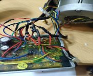
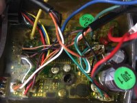
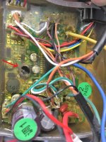
I opened the motor and found the remains of an exploded cap! See picture: IMG_1783.JPG
(Normally, this cap is labeld: 8I - 100 - 16J. I assume this would be a 100µF 16V cap; everything else looks optically ok on the pcb)
So, I thought the controller is dead. (I can not do a full test of the controller, as this is a 48V controller and I have only 36V batteries...) Oddly, though, it must still (partly) work, as it communicates with the display: When I connect a 36V battery and switch it on via display, I get an undervoltage Error08 and I can switch support-levels. (Only the controller 'knows' the rated voltage of 48V, so the display must have gotten that info from the controller)
Also, I verified that the controller produces the correct 5V for the ST µController when fed with 36V and switched on via display.
So here are my questions:
1) Does anyone know in which part of the controller circuitry the quoted cap might be involved in?
2) Do you agree with the interpretation label "8I - 100 - 16J" means 100µF / 16V?
3) Do you have an idea why the µcontroller still works (-> communicates w/ dispaly), but refuses to communicate via SWM pin for programming?
4) Any trouble-shooting ideas?
 
Has anyone thought about making a new axel with spline crank arm connections? Square arm cranks are getting hard to find these days and maybe a new axel could be stronger (less chance of breaking).
 
RicMcK said:
Has anyone thought about making a new axel with spline crank arm connections? Square arm cranks are getting hard to find these days and maybe a new axel could be stronger (less chance of breaking).

A larger spindle diameter would be more resistant to breaking-- but keep in mind that the incompetent designers of the TSDZ2 used a spindle diameter 2mm smaller than what other square taper, sealed bearing spindles use. So they almost surely designed in physical constraints that would make it impossible to use a larger diameter spindle (whether square taper or splined).

Square taper cranks are absolutely not hard to find. They'll be freely available long after all today's splined spindle standards have passed into history. I don't use them because they're underbuilt for my weight, but square taper cranks are here to stay.
 
i have a 8 pin vlcd5 but i am a little bit annoyed by it(it sucks in sunlight because it blinds you, also it's been unresponsive lately. (the kph freezes for few minutes then works again.) id like to exchange it for vlcd6, i would like to know if it works
 
Matze_Senpai said:
i have a 8 pin vlcd5 ..... id like to exchange it for vlcd6, ....
imho only the vlcd5 has an 8-pin and 6 pin version.
Vlcd6 has only a 6 pin connection.
So if possible you must find a conversion cable or solder the 8 -pin yourself.
 
endlessolli said:
Hi everyone; I have an odd problem:
...
I opened the motor and found the remains of an exploded cap! See picture:
...Oddly, though, it still seems to work properly! (I verified that it spins the motor w/ walk assist)
So here are my questions:
....

After some digging and poking, I can now (paritally) answer my own questions here, just in case it helps someone else in the future:

1) in which part of the controller circuitry is the blown cap involved in?
-> This is the smoothing cap for the 6V light power supply (green wire from speedseensor cable)
2) The cap is rated 100µF / 16V, as verified on other pics from the internet
3) Why does the µcontroller still work, but refuses to communicate via SWM pin for programming?
-> Measured SWIM Pin and it is shorted to GND (internally in the µcontroller); maybe some ESD accident / error in wiring in the past?
(That could also explain the blown cap, if the same happened on that wire...)
4) Any trouble-shooting ideas?
-> I ordered a new µcontroller (STM8S105S4T6C) and will try to replace the old w/ the new one...

One question to the community, though: Does anyone know, if this µcontroller is programmable (and readable) when only GND, 5V & SWIM are connected? (I.e. programming prior to soldering onto the PCB, i.e. all other pins are floating.)

InkedIMG_1783.jpg
 
Question was about if a square bb would work with tsdz2. However, the person I was going to buy the bike from upped the price.
 
Elinx said:
Matze_Senpai said:
i have a 8 pin vlcd5 ..... id like to exchange it for vlcd6, ....
imho only the vlcd5 has an 8-pin and 6 pin version.
Vlcd6 has only a 6 pin connection.
So if possible you must find a conversion cable or solder the 8 -pin yourself.

I'm in the same boat. Looking to go to the VLCD6 after briefly using my VLCD5. Does anyone know if this bafang 1T2 cable would work from converting 8 pin to 6 pin?

https://www.amazon.com/BAFANG-Extension-Cable-Drive-Motor/dp/B09J2FFLBT
 
Back
Top