
You are using an out of date browser. It may not display this or other websites correctly.
You should upgrade or use an alternative browser.
You should upgrade or use an alternative browser.
Nucular Electronics owner's thread (setup infos, FW updates, links etc.)
- Thread starter madin88
- Start date
j bjork
1 MW
HK12K said:When you said to be sure to be sure to get the pwm outputs, is that the same as adding the PWM IO PAS wire option, or something different?
I don't really understand how the pwm driver thing works. I know what pwm is but am lost in regards to how it's used in this application for fans and lights and such, and the 30v notation just confused me further.
You are probably right about pwm io pas wire option.
The pwm outputs from the controller cant take much load, so you need a "booster" to actually use them for something. Those that nucular sells can handle up to 30v, so if you have a 12v system for lights or whatever they are fine.
But you dont need them until you need them.
But if you want to use the pwm later, dont have the wiring and a potted controller.. Then you have a problem.
If you dont have a potted controller you can always add the pwm or input wirings later.
tylerwatts
100 W
- Joined
- Sep 14, 2012
- Messages
- 212
Hello owners.tylerwatts said:Hi VasiliSK
Do you have any experience running big RC motors with your controllers? Such as Turnigy CA120 outrunner with low inductance values? What pwm frequency can/do your controllers run at?
Please share any working examples or owner threads of such combinations.
Thank you
Cheers
Tyler
Can anybody share experience of running high pole count and low inductance motors with a Nucular controller please?
Thanks
Cheers
Tyler
Hy guys,
I am trying a Heinzman PMS 100 brushles with a 24 F. I got a problem with the hallsensors. In the automode he give a time out and the shaft isn't moving anyway. I have a fault "hallsensor" probebly having the wrong combination in connecting Hallsensors motor toward controller. what can I do without blowing the sensors.
I am trying a Heinzman PMS 100 brushles with a 24 F. I got a problem with the hallsensors. In the automode he give a time out and the shaft isn't moving anyway. I have a fault "hallsensor" probebly having the wrong combination in connecting Hallsensors motor toward controller. what can I do without blowing the sensors.
Thanks again.
Are these boosters out in the wild yet? I'd love to learn more about how they work in practice. A wiring diagram would be especially enlightening, if such a thing exists. I'm now envisioning them as essentially a computer controlled relay but need a better understanding before I can even think of deploying them.
Also, as for adding wires later (assuming no potting) are there headers or connectors on the board for plug-in expansion or would it require soldering to the pcb?
j bjork
1 MW
https://drive.google.com/file/d/1vonyWZPs-DGDJqb7it93iebNcyarL1_d/view
There are connectors on the bord, see link above.
I don't have any of these pwm bords myself, but I have others just like them I guess.
It is just small boards with mosfets you use instead of relays. When you control them with pwm in, you get pwm out.
So if you have 12v to feed them, and maybe 50% pwm you get 6v out. Well, actually you get 12v, 0v, 12v, 0v very fast. So a fan motor or a light bulb will react as if they were fed with 6v.
I think the advantage of pwm is to be able to vary the power of the lighting or the speed of a fan. The advantage is also to be able to supply different lighting systems whether they are 6v, 12v, 24v because the pwm allows you to adjust the voltage from 0 to 30v.
cheeko
100 W
serious_sam said:From the Nucular wiki: "delta voltage relative to the maximum, at which when the controller is turns on, will reset the watt-hour consumption".
The way I read that, is if you turn on the controller and you battery voltage is between Vmax and Vmax-dv, your Wh will reset.
Your Vmax should be set to 84V for a 20S pack. Try setting dv to 2 volts. Then if you turn on the controller, your Wh should only reset if your battery is above 82v.
Still resets every time at this voltatage, could it be the BMS stopping power to the unit seems to keep the total WH untill reset through, Im Confused


Hi guys !
I mounted a small capacitor preload resistor on my Nuc 24F.
I used the old diesel engine preheating relay of my Microcar to activate the preload resistor.
I noticed that the controller does not want to light up if the voltage is above the LVC.
I need to preload at around 60V for a 20s battery, so that my controller turns on.
If I preload at 70V the controller stays off and even when I unplug the controller, the capacitors stay charged.
I have to empty the capacitors through a resistor or a bulb to be able to turn on the controller.
Have you ever noticed this?
What explains this phenomenon?
My preload resistor is connected between the terminals of the 72V ON / OFF relay
Got a Magura Throttle but the first 10 degrees turn there is no reaction then after 10 dergrees he starts to react.
Got 250 Ohms resitors in the + and ground but that doesn't make any difference. Can I adjust this in the parameters?
Btw it is a 24F Nucular controller
Got 250 Ohms resitors in the + and ground but that doesn't make any difference. Can I adjust this in the parameters?
Btw it is a 24F Nucular controller
")
Xtr6 said:Got a Magura Throttle but the first 10 degrees turn there is no reaction then after 10 dergrees he starts to react.
Got 250 Ohms resitors in the + and ground but that doesn't make any difference. Can I adjust this in the parameters?
Btw it is a 24F Nucular controller
Yes it is possible to adjust the minimum activation speed of the accelerator.
Caution ! If you set too high, the bike drives alone. :lol:
VasiliSk said:PITMIX, schematic designed this way to turn on when voltage rises
Thank you Vasili I suspected there was something like this
Can someone let me know if and how
-to connect a front light and a rear lamp, with a brake light function with a control button (Turn off and on)
12 volt lighting system. (at the moment a front light would be good enough)
Do I need to get a DC/DC converter Any recommendation?
How does that connect to the battery leads? Do you need to get a "Y" cable to split up the main power lines. Where do you find these?
I read somewhere that it might be possible just to connect the lamps straight to the PWM.
lukashanak said:Things i've done for fast throttle response:
Running torque mode
In control modes acceleration limit set to 0
Shortened my throttle so max volt on WOT is only 2.8 not 4.4v and made auto throttle calibration for this voltage.
And adjusted PID. FOC Ki to 120.
How exactly did lukashanak "shorten" his throttle, please ?
lukashanak
1 W
- Joined
- Apr 11, 2019
- Messages
- 59
csc said:How exactly did lukashanak "shorten" his throttle, please ?
I just mechanicaly shortened way of throttle with screw added inside as stop. So I cant give full throttle with 4.4v, but only 2.8v. And after that auto throttle calibration detect full throttle voltage 2.8v and set WOT on this lowered voltage.
Hi,
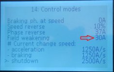
Need some help getting field weakening working.
I am using the 12F with a cyclone 3000 mid drive motor, currently with no load.
I have set:
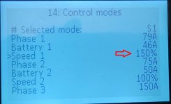
Speed 1 to 150%
field weakening to 30A
Reference speed very high so it will not limit the motor speed.
I am seeing a very small increase in motor speed (about 5%), much much less than with stock controller. if I reduce "Speed 1" the controller responds correctly.
What am I missing?
Thanks!
Need some help getting field weakening working.
I am using the 12F with a cyclone 3000 mid drive motor, currently with no load.
I have set:
Speed 1 to 150%
field weakening to 30A
Reference speed very high so it will not limit the motor speed.
I am seeing a very small increase in motor speed (about 5%), much much less than with stock controller. if I reduce "Speed 1" the controller responds correctly.
What am I missing?
Thanks!
Attachments
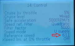
madin88 said:You have set reference speed too high.
I changed it to 50, it has no effect. The speed reading on the display is about 195 at max throttle.