NYX Cromotor Max-E Build

ridethelightning said:
because of this, i have recently been toying with the idea of having the controller mounted on a bracket from the seatpost, where it comes out near the shock.
this could then be incorporated into mudgard mount/structure aswell.

this would be better practically, but perhaps loose a few points asthetically(?)
Im still seriously considering it.

+1 to the gasket around the hatch opening.

this project is also one stall after another for me, so much to figure out if you want to do it right first time, and not end up with a swiss cheese nyx :lol:

I'd like to see how you do it if you ever do mount it by the seat post, let me know if you ever go through with it. My first ebike has a "cargo rack" style enclosure for the controller, I'll get a few pictures of it but don't think it is much different than a few others have posted, but maybe there aren't as many as I thought, regardless I'll get a picture of it up for you.

macribs said:
For the controller the consensus seems to be to have the wires downward so that watersplashes/rain/morning dew or whatever don't travel on the wires and try to enter the controller as it would do if wires was pointing upwards. I guess if you are set on routing the cables in a way that would make more sense with the wires sticking out on top, rather you could mount the controller with wires exiting at the bottom, make half a loop so the lower point of the half loop is lower then the lowest point of controller and route the cable along the side of controller to your favorite place of entering the frame.

Come to think of it, madin88 did a clever thing with the max-e. He got his adaptto in the frame but connected to a heat sink. Then the heatsink itself is mounted outside the frame. No need to worry about water. You could do the same, even use heat pipes for connection. And from the pics it does not appear that madin's solution is eating up much space. This way your controller could be safely tucked away inside the frame, protected from the elements yet still get air cooling. If you use heat pipes for connecting the controller to the heatsink you will get even more cooling - and a closed loop cooling setup for the controller.

Thanks macribs, that was my understanding to the logic of pointing the wires downwards too, that's a great description I appreciate it.
That is a really nice ride Madin88 has there! I've read a lot of his posts and have been meaning to drop him a line for his work with the Adaptto's Owner's thread. He's got some great ideas, I hope to get more involved outside this post when I get the majority of it under control and knocked out of the way...shouldn't be soon here's an update a few more days...if it runs that is ha, and than just some brackets and water protection stuff but should be able to get a few passes down the street on a nice day in a few more days.

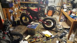
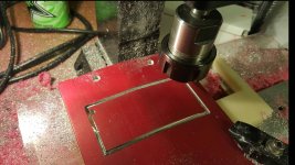
Ended up powder coating the clamps Red myself. Always wanted to powder coat and happy with the results so all in all I'm pretty pleased for my first go at it.

It's starting to look more like a bike. The controller is mounted temporarily and I'm half rushing this just to get it running at this point, and half rushing because I may be moving in the very near future..still under discussion with the wifey...so understand that some of what you see is just to get me to the point of knowing that it runs. Things like water protection and bash guard for the controller and fenders n all are still going to get done and I still want to have it to have that clean look like it was made as a complete bike...will have the updates for now I'm under the gun a bit..more pics to come very soon possibly a video too..

BTW keep an eye out for me, my next post may be an SOS trying to get it running. Hoping to get a video of that process too in case it helps someone or someone can see where I went wrong if I do..not sure how I'll be working on it while holding the camera but we'll see.
 

Attachments

  • NYX-31.jpg
    NYX-31.jpg
    388 KB · Views: 2,658
standing by to stand by for the sos :lol:

should be easy though, the adaptto should be pretty simple to get running, as long as you know to avoid doing a few key things.

I have 244samsung 30Q on the way for my nyx, 22s12p pack.

I decided to ditch the 18650 cells spacers, so it means i can now get the huge pack, max-e, ac adaptor for 12vdc and charge coil all in the frame.

the next trick is all the cable routing, which I have a very good plan for, using these;
http://shellys.buy.cgsdigital.com/iz5aba0c9-metal-cable-glands-multi-hole-amp-flat-hole-okq13-metric-pg-g-pf-and-npt-thread-images.html
multi hole cable gland for the phase wires +halls, out the back of the frame to the swingarm. I think i need the 4*6mm hole m25 size there.
for the display cable, dc and switch, ill try a 3*4-5mm hole, m16size to be lower profile, just behind the steerer somewhere. oh and I might mention, they are an absolute prick to get hold of in the right size, unless you want500 of them :|

then ill need to cut some vents to let heat out, probably under the front above the tyre, and in the bottom of the seatpost bracket.


macribs said:
Great update, don't know about other but I read every word of your updates so pls continue. And I read it all depsite the fact that I don't own a NYX myself but a Vector. But your vision for this bike is what my dream Vector would look like, beefy fat tires. Man I look forward to see this build completed.

For the controller the consensus seems to be to have the wires downward so that watersplashes/rain/morning dew or whatever don't travel on the wires and try to enter the controller as it would do if wires was pointing upwards. I guess if you are set on routing the cables in a way that would make more sense with the wires sticking out on top, rather you could mount the controller with wires exiting at the bottom, make half a loop so the lower point of the half loop is lower then the lowest point of controller and route the cable along the side of controller to your favorite place of entering the frame.

Come to think of it, madin88 did a clever thing with the max-e. He got his adaptto in the frame but connected to a heat sink. Then the heatsink itself is mounted outside the frame. No need to worry about water. You could do the same, even use heat pipes for connection. And from the pics it does not appear that madin's solution is eating up much space. This way your controller could be safely tucked away inside the frame, protected from the elements yet still get air cooling. If you use heat pipes for connecting the controller to the heatsink you will get even more cooling - and a closed loop cooling setup for the controller.

Madin88's heatsink.
GRS6R5h.jpg


Close up of heat sink
jaMGfXr.jpg


Not much real estate taken up by the controller as you can see.

HuRGKSH.jpg

i must say, that does look like an awesome way to mount the controller too, I might look into that aswell
 
ridethelightning said:
standing by to stand by for the sos :lol:

should be easy though, the adaptto should be pretty simple to get running, as long as you know to avoid doing a few key things

Any of those few key things come to mind??

ridethelightning said:
the next trick is all the cable routing, which I have a very good plan for, using these;
http://shellys.buy.cgsdigital.com/iz5aba0c9-metal-cable-glands-multi-hole-amp-flat-hole-okq13-metric-pg-g-pf-and-npt-thread-images.html
multi hole cable gland for the phase wires +halls, out the back of the frame to the swingarm. I think i need the 4*6mm hole m25 size there.
for the display cable, dc and switch, ill try a 3*4-5mm hole, m16size to be lower profile, just behind the steerer somewhere. oh and I might mention, they are an absolute prick to get hold of in the right size, unless you want500 of them :|
Hey nice find! I'm jealous those would have made my routing much cleaner..bummed that I committed and have all my holes drilled :cry:

This isn't probably as big of a hurdle for most other members I imagine, but just to note once those connectors are cut, those wires are fragile! I soldered my throttle so I started with the display 4 pin plug first and having some luck the wires leading from the Max-E are a little more durable/ thicker strands, but the wires exiting the display to the Max-E have just a few strands of "hair sized" wire..

So, because the Max-E wires are fairly short and this is now a "weak link" I extended the wires from the Max-E to solder to the display wire in the frame....not the end of the world and I have been trying to take my time to be gentle, I'm just concerned that if I encounter a problem, I will have these connections where I eliminated the connectors to factor if I have to diagnose anything.

We'll see, gonna head down and chip away some more. This is one of those times I wish I would have taken my own advice and made sure everything worked before going around and messing with everything...I know better than this (speaking from experience wiring my first Ebike :roll:) but I'm just hoping that I have been cautious enough with each step...about all I can do I think at this point now keep rollin with it...
 
walkev85 said:
Any of those few key things come to mind??

yeah, mainly to do with wiring of the bms. its critical that you get the order right when you plug and unplug the jst connectors and any series pack connectors.

general rule- unplug all jst connectors from the board before messing with any series connections to avoid frying bms boards.

better not power up without installing precharge resistor.

NEVER try to attempt an autodetect cycle with the charge coil circut engaged.(I found out the hard, 600dollar way :| )

NEVER play with the brake/throttle while in charge mode, can dammage it.

there are probably other things but these come to mind straight up :)
 
Rix said:
Subscribed, talk about bad ass. This thing is sick.

Thanks Rix man! This is good stuff, glad to have another experienced member following along. Aren't you lucky with Interbike right your Home State?

I'm gonna kick this rant off with the good news first...Got all wiring done to the point where I can get 'er powered up with no fireworks, pops, blow ups, or even sparks so despite the bad news which I don't think it's that bad (yet), I decided I would call it a day with no expensive parts broken.

No lie I had safety goggles, gloves, long sleeves, linesmans and fire extinguisher in reach. The site was probably picture worthy but just like riding when I dress to crash.

So went through the menu put my battery info and profiles in etc. went to autodetect and then THROTTLE ERROR. Cut the microswitch wire on the Domino n took care of that.

Twist the throttle again, now the motor squeals and pulses like it's ready to go and HALLS 2 ERROR shows. Tried switching the direction n no dice. Couldn't find the Halls 1-2-3...screen for the life of me from the health menu. Tried double checking my High and Low cutoffs and they seem appeared correct. I got the tail suspended from straps so I couldn't tell if it was swinging or rocking back next forth come to think of it.

I have the BMS board wired to the controller but none of the balancing leads are plugged into it. Think that is the first thing I will try but they aren't plugged in because I didn't make the enclosure/mount. Da man Cedrick at NYX suggested using Phenolic material to do this so I stole the cutting board from the kitchen but was just to tired to go back at it again and make it up right now...

As I mentioned I eliminated all the connectors except the bullets and soldered everything so I couldn't just unplug the board.

I didn't want to take a bunch of screen shots and spend forever resizing them when I I have loose ends that could be the culprit. I don't know if my regen settings were off for the throttle issue but I triple checked it and that created a problem maybe my sensor wires are wrong..Pin 1 = Yellow, Pin 2 = Green, and Pin 3 = Blue based from the Adaptto Owners Forum.

Sorry, will put the screen shots, pictures, and video of its running state next round. I gotta chalk it up as a success for the day for not frying a bunch of money n get some rest..I dunno if that's noobish or what I don't care had to Google what that meant when I first saw that kinda funny. Unless anyone wants to throw ideas out there I'll give it another go tomorrow n see if I can trouble shoot my way through it before I go on and on speculating.
 
walkev85 said:
Rix said:
Subscribed, talk about bad ass. This thing is sick.

Thanks Rix man! This is good stuff, glad to have another experienced member following along. Aren't you lucky with Interbike right your Home State?

I'm gonna kick this rant off with the good news first...Got all wiring done to the point where I can get 'er powered up with no fireworks, pops, blow ups, or even sparks so despite the bad news which I don't think it's that bad (yet), I decided I would call it a day with no expensive parts broken.

No lie I had safety goggles, gloves, long sleeves, linesmans and fire extinguisher in reach. The site was probably picture worthy but just like riding when I dress to crash.

So went through the menu put my battery info and profiles in etc. went to autodetect and then THROTTLE ERROR. Cut the microswitch wire on the Domino n took care of that.

Twist the throttle again, now the motor squeals and pulses like it's ready to go and HALLS 2 ERROR shows. Tried switching the direction n no dice. Couldn't find the Halls 1-2-3...screen for the life of me from the health menu. Tried double checking my High and Low cutoffs and they seem appeared correct. I got the tail suspended from straps so I couldn't tell if it was swinging or rocking back next forth come to think of it.

I have the BMS board wired to the controller but none of the balancing leads are plugged into it. Think that is the first thing I will try but they aren't plugged in because I didn't make the enclosure/mount. Da man Cedrick at NYX suggested using Phenolic material to do this so I stole the cutting board from the kitchen but was just to tired to go back at it again and make it up right now...

As I mentioned I eliminated all the connectors except the bullets and soldered everything so I couldn't just unplug the board.

I didn't want to take a bunch of screen shots and spend forever resizing them when I I have loose ends that could be the culprit. I don't know if my regen settings were off for the throttle issue but I triple checked it and that created a problem maybe my sensor wires are wrong..Pin 1 = Yellow, Pin 2 = Green, and Pin 3 = Blue based from the Adaptto Owners Forum.

Sorry, will put the screen shots, pictures, and video of its running state next round. I gotta chalk it up as a success for the day for not frying a bunch of money n get some rest..I dunno if that's noobish or what I don't care had to Google what that meant when I first saw that kinda funny. Unless anyone wants to throw ideas out there I'll give it another go tomorrow n see if I can trouble shoot my way through it before I go on and on speculating.

That sucks, I have not experience with the Max E....yet, its coming up on a future build I got going down this winter. That said, I am going to Pm Alex about this, he is the guy that set up my Adapto MAXE and MXUS 4t up for direct plug-n-ride and will be building me my battery with the adaptor BMS at some point this winter. Chances are, if he can't help you with your controller problem, controller may need to be sent back to Adapto Labs.
 
steady as she goes..

Hall error 2 has a specific meaning I think.

It will not be because you got the hall wires/phases in the wrong order, it doesnt matter which way they go.

It could be a bad solder joint on the hall wires where they join the pcb in the controller(I had this happen) or in the plug somewhere, perhaps a short across the 5v and gnd or maybe something isnt soldered right.

also its possible one of the halls in the motor is faulty/broken from production. I have seen this too with the cromotors.

opening the controller voids warranty so i would not really advise it.

also possible its a blown resistor in the controller but same applies.

allex is the guy to ask. sending it back will perhaps be the best course of action if all the other possibilities are exhausted.
 
ridethelightning said:
steady as she goes..

Hall error 2 has a specific meaning I think.

It will not be because you got the hall wires/phases in the wrong order, it doesnt matter which way they go.

It could be a bad solder joint on the hall wires where they join the pcb in the controller(I had this happen) or in the plug somewhere, perhaps a short across the 5v and gnd or maybe something isnt soldered right.

also its possible one of the halls in the motor is faulty/broken from production. I have seen this too with the cromotors.

opening the controller voids warranty so i would not really advise it.

also possible its a blown resistor in the controller but same applies.

allex is the guy to ask. sending it back will perhaps be the best course of action if all the other possibilities are exhausted.

So I plugget the BMS board in and that appears to be monitoring correctly although I didn't try anything in the way of charging yet.

Pulled the Fluke out, which I'll note quick having an accurate Multimeter is what solved my trouble shooting on my first bike when my little cheap one that got tossed around and mixed in my toolbag when I was a construction laborer wasn't reading abnormal results.

So I have the controller ON and went from Pos+ to GND and have 4.422V. From GND to Blue, Yellow, and Green Halls all read 4.422V. They don't switch or change when I move the wheel nor when I leave the wheel stationary to check what each read...

I have one Temp Sensor Wire to GND which I replaced with KTY that came with the Adaptto and is reading on the display. Could I have done something with that? If a hall sensor was bad, I thought they would all read 0V? All three not switching is confusing me though. I'm going to shoot Allex a message like Rix suggested n see what he thinks. Thanks for the ideas and suggestions.
 
Here's my settings...I changed Hall Reverse and Inverse to off after doing another reset and now it doesn't squeal the j wheel just pulses...so maybe it's a setting...In the meantime I'm going to try and find out what these different advanced settings are and get a printout of the manual to write on.
 

Attachments

  • Main Screen.jpg
    Main Screen.jpg
    41.6 KB · Views: 2,521
  • Health Monitor 1.1.jpg
    Health Monitor 1.1.jpg
    51.1 KB · Views: 2,521
  • Battery Monitor 1.1.jpg
    Battery Monitor 1.1.jpg
    47 KB · Views: 2,521
  • Stats Watt Meter 1.1.jpg
    Stats Watt Meter 1.1.jpg
    48.2 KB · Views: 2,521
  • Halls Error 2 Result.jpg
    Halls Error 2 Result.jpg
    49.9 KB · Views: 2,521
  • Profiles Setup.jpg
    Profiles Setup.jpg
    59.7 KB · Views: 2,521
  • BMS Settings 1.2-1.jpg
    BMS Settings 1.2-1.jpg
    56.1 KB · Views: 2,521
  • BMS Settings 2.2.jpg
    BMS Settings 2.2.jpg
    40.8 KB · Views: 2,521
  • Advanced Settings 1.5.jpg
    Advanced Settings 1.5.jpg
    54.3 KB · Views: 2,521
  • Adv Settings 2.5.jpg
    Adv Settings 2.5.jpg
    50.6 KB · Views: 2,521
  • Adv Settings 3.5.jpg
    Adv Settings 3.5.jpg
    64.6 KB · Views: 2,521
  • Adv Settings 4.5.jpg
    Adv Settings 4.5.jpg
    36.8 KB · Views: 2,521
  • Adv Settings 5.5.jpg
    Adv Settings 5.5.jpg
    61.2 KB · Views: 2,521
ridethelightning said:
steady as she goes..

It could be a bad solder joint on the hall wires where they join the pcb in the controller(I had this happen) or in the plug somewhere, perhaps a short across the 5v and gnd or maybe something isnt soldered right.

also possible its a blown resistor in the controller but same applies.

Above is the most common problem, Some wrong connection and the Resistor blow:
Here is the video with hall 2 error
https://www.youtube.com/watch?v=UE90LU09JYo
https://www.youtube.com/watch?v=sg5BiHMm624

He had to replace(if I remember correctly) the blown resistor inside the controller.


Measure voltage between power ground and halls ground while hall sensor is connected.
If voltage is more then 1V, means there was a short circuit of hall wires to somewhere else (phase wires). Check isolation of halls wires. Remove back cover of the controller (without wires) and replace R113 (R113 is near the fixing screw). The value of the resistor is any within range 2-8 ohms.
Note if you do this(not send it in), warranty will void
Photo of resistor
http://electrotransport.ru/ussr/images/1/zvhkrb.jpeg

Oh, and you got big FAT "R" on the main screen, Disable the "Set range" option. With it it enabled the controller will limit your power so you can get to your destination with non empty battery. You can turn it on later when you feel that with a particular ride, you are not sure if the battery will get you back.
 
If it is than I didn't have any luck there...actually I didn't get any reading..I'll go through and check all my solder connections. I spent a lot of time making sure that I that they were all shiny and threw a little epoxy on under the shrink wrap for some additonal strength (not sure if that was the right thing to do or wise..well not now at least since it isn't working) so I hate to admit it but not to proud to go back and check em so I will. In the meantime I'll see what Adaptto says about the warrany.

Thanks again Allex appreciate it.
 
i guess it depends on if you like wheelies or stoppies better.....i like wheelies.....re the levers....ive hd mine auzzie style (left hand rear brake) since i had enough power to pull "monos" :mrgreen: :mrgreen: :mrgreen: :mrgreen: rt now im working on sustained 60kmh wheelies ....

awesome build!! over tired imo, you are saving alot of weight with your other parts it leans toward a super light build ....al rims 1.4 17", thinner spokes and shinko 2.5"s just my opinion.....your gonna have a blast !!!!those meats will rip the rocks i guess !!


ps i love my kelly 96351 less than half the price of adappto....
 
hydro-one said:
i guess it depends on if you like wheelies or stoppies better.....i like wheelies.....re the levers....ive hd mine auzzie style (left hand rear brake) since i had enough power to pull "monos" :mrgreen: :mrgreen: :mrgreen: :mrgreen: rt now im working on sustained 60kmh wheelies ....

awesome build!! over tired imo, you are saving alot of weight with your other parts it leans toward a super light build ....al rims 1.4 17", thinner spokes and shinko 2.5"s just my opinion.....your gonna have a blast !!!!those meats will rip the rocks i guess !!


ps i love my kelly 96351 less than half the price of adappto....

96351...not two times the weight and size???
 
I think the pwr and halls ground allex is referring to are the black and red wires in the halls plug to motor.
pwr ground would then be the black battery cable(?)

the bad solder joint that I found to be the cause of error one time was inside the controller, where the halls wires join the pcb. it was basically hangn' free there from bad manufacture :|

check everything for continuity.

in health screen , where i t says HALLS: 011,H6....

do the all 0s and 1s cycle on and off in order when you turn the wheel? if not , that will indicate a specific problem- bad hall connection somewhere.
 
hydro-one said:
i guess it depends on if you like wheelies or stoppies better.....i like wheelies.....re the levers....ive hd mine auzzie style (left hand rear brake) since i had enough power to pull "monos" :mrgreen: :mrgreen: :mrgreen: :mrgreen: rt now im working on sustained 60kmh wheelies ....

awesome build!! over tired imo, you are saving alot of weight with your other parts it leans toward a super light build ....al rims 1.4 17", thinner spokes and shinko 2.5"s just my opinion.....your gonna have a blast !!!!those meats will rip the rocks i guess !!


ps i love my kelly 96351 less than half the price of adappto....

Hey thanks Hydro-One, yeah could end up being overkill and worth trying something a little lighter. I hesitated from the gate but just wanted something wild and a bit different I guess ya know..I think I got the brakes worked out with my Y fitting but it hasn't been tested yet to know for sure just me squeezing them so the lines aren't getting hot or anything. Should be fun trying to wheelie around...how is it without listening to an engine to slip the clutch? Did it take a while? Kinda curious what it will be like. Figured I would just do like I did starting out on my gixxer years ago with my legs out to walk it out if I loop it..

ridethelightning said:
I think the pwr and halls ground allex is referring to are the black and red wires in the halls plug to motor.
pwr ground would then be the black battery cable(?)

the bad solder joint that I found to be the cause of error one time was inside the controller, where the halls wires join the pcb. it was basically hangn' free there from bad manufacture :|

check everything for continuity.

in health screen , where i t says HALLS: 011,H6....

do the all 0s and 1s cycle on and off in order when you turn the wheel? if not , that will indicate a specific problem- bad hall connection somewhere.

Ohhhh alright...well than yea in that case I had the same 4.422V when I tried that..damn..and turning the wheel does nothing I see why I couldn't find that screen before but I did notice them switching in the one video Allex shared and understand what the manual was trying to say now..motor sounds just like that video..I was calling it Pos+ a few posts above..I was thinking that power was up at the display. Guess I'll have to open the motor again to see if messed that up putting the temp sensor in cause the the connections were good continuity wise.

Maybe the Adaptto is real sensitive and need to check the resistance of each and see if one of those is cutting it close but I didn't think to do that cause the Fluke is pretty sensitive I think..I would have to check what strength signal it measures.

Ah this kills me not knowing. I dunno we're moving out 1st week of October and have a ton of stuff to pack not looking forward to it and I didn't get to bring it to any charity rides which kills me even more. I'll have to see what Adaptto says about the warrany. I scooped it up in March but was off the For Sale section on ES here cause they didn't have PayPal and my bank doesn't do International wire transfer so before I thought of sending a money gram through western union or something I already pulled the trigger on this one. So anyways if they don't accept it for warranty I'll give that resistor a shot if opening the motor doesn't reveal any issues.
 
Actually here we go hall sensor test: http://www.ebikes.ca/learn/troubleshooting.html

Allex said power ground and halls ground so that may have been right how I tried it. According to this I should get between 4-5V but I see in the picture the Phase wires are disconnected which mine weren't when I tested it. I also had constant voltage and no switching when I spun the wheel just the same reading at all 3..that sounds like a short but I don't see how I got all 3 facocked pulling the cover and utilizing the wires from the original temp sensor. I'll try anything though at this point and worth ruling out.
 
id check the internal wires of the motor as first call. make sure everything is as it should be.
if you have another controller around, try running the motoer on that even..yeah i know, its a bitch to get all the plugs rewired and then get the damn combos right.
at least that way you will know the motors ok and can start looking elsewhere.

at least check for continuity between wires including phases/halls the lot where there should not be any.
....and make sure there is where it should be :)

id assume the controller is innocent first before proven guilty, same goes for the actual hall sensors themselves.
 
You're right and think I'm going to do just that and sit my old bike next to it and I used the same connectors on this bike as I did that one for the halls and temp guage so it would just be a matter of throwing 3 bullets on the phase wires.

Either way it looks like I just need to get step back and regroup for a bit and stop trying to get it done overnight. I already took the shortcut mounting it without making the brackets and started getting excited early.

Won't hurt learning more about the controller and being more involved with that as opposed to sending it back. That's a lot of downtime to resolder somethings and to have the opportunity to seal it up properly. I don't have to recreate it just mimic, fix, or improve what's already done ya know.

It'll get done just won't be instantly.
 
Alright....so everything's gravy and back on track..auto detect did its thang n I've got myself some staring input values to work with manually. Didn't hammer it or anything just let it chill on the Economy mode I set (Profiles and battery settings courtesy of Morati with the NYX MXUS) because that nice wire job I did is hagin n danglin everywhere with a bunch of electrical tape over all the wires I knicked to get a sweet spot for the meter probes.

So right as I said when I cut those connectors off that they were fragile...and I shouldn've made sure it worked first before I even tried starting it..wouldn've saved me a a lot of trouble. The hall wires were either barely hanging on in the controller with one broken off. I cursed myself off when I cut the connectors of and saw how fragile they were and let's just assume that I wasn't careful enough. Who knows who cares except that it's fixed and somehow didn't have one mess with that resistor which is something I'm thankful for.

Back on track and my girl must love me cause I haven't done shit to move out yet and back trying to get what I I have done.

Alright I know Doc has the lights for his BMS shining up through the holes he made on his hatch..as usual very clever guy. So ya now how Ferrari, Corvette ZR1, etc have a clear panel on the engine hoof to show off what's inside? That's more what I am going for and solves the place to mount the BMS. I'm actually giving my mill some time for the motor to cool off as I write this..but this is what I did quick and I cut a piece of glass to recess in the back of the hatch, spray some black plast-dip over my..oh yea kitchen cutting board ha, and stick a little very light tint on the glass for a little extra something, seal it, and finally gaskets.

After that I'll go back and clean up all these wires again..probably just temporary stuff to make sure it still gets some miles on it without issues..and that'll probably be all I have time to do for a little while..but don't have to to walk away ashamed at this point at least.
 

Attachments

  • 20150916_182921.jpg
    20150916_182921.jpg
    279.7 KB · Views: 2,436
GREAT NEWS!
so its working.
If it was the hall wires in the controller where they join the pcb, I think it was not your fault.
i have seen this a couple of times, i think its a quality controll issue at the factory where adaptto gets them made.
autodetect is raelly only good for getting the halls/phase combos right. its ability to detect the correct settings is so far highly limited at best with the current fimware options.

manual tuning cromotor settings-
https://endless-sphere.com/forums/viewtopic.php?f=6&t=53867&p=844282&hilit=cromotor+settings#p844282

will be keen to see how the bms window looks.
I was considdering something similar butwill probably use lexan or some scratch resistant tinted platic, and a o-ring type compression seal around the edge.
then there is the gasket around the hatch...no mean feat either.

keep it comming :D
 
ridethelightning said:
GREAT NEWS!
so it's working.

manual tuning cromotor settings-
https://endless-sphere.com/forums/viewtopic.php?f=6&t=53867&p=844282&hilit=cromotor+settings#p844282

will be keen to see how the bms window looks.
I was considdering something similar butwill probably use lexan or some scratch resistant tinted platic, and a o-ring type compression seal around the edge.
then there is the gasket around the hatch...no mean feat either.

keep it comming :D

Yup it's working and what a feeling of relief when you first get one of these projects going for it's first time..it's awesome.

Thanks for the link, I thought I came across that before and remember I wanted to revisit it but I was fumbling through the Adaptto forum. It'lol be nice to compare..you're right about the manual tuning from what I've read and can remember reading a lot of people missing this crucial step.

Let's hope the BMS and charging work now! Actually I forgot I wanted to ask if someone could send me a pick of the Eaton's DC and AC cables and where/how they are connected..It's been a while since I bought it and honestly haven't given it a good look yet but I wold still appreciate the help with saving some time researching.

Ugh how bout it..I have the perfect size piece of lexan scrap that I used for the sides of my tool drawers so I see what's in there easier and I couldn't find it. So I said hey babe what are we doing with this extra computer scanner? Nothing she says so went stole the glass out of it haha. But yea Craigslist has scraps pop up every now and again but also think anything over 3/16" thick you can drill and tap? Great stuff Lexan..so you seem to have all my ideas what I am going to do next? Ha just messin around but yea it will be recessed from the back and just going to use commercial glazing (window) caulk for Alum and glass storefronts and such should hold up plenty I'm hoping at least probably about 3/8" boarder lip around the back you don't see from the top.

I'm running this one by hand cause I can't afford a G code error or something on my only hatch with that pitched angle so we'll see hope I can put a decent routered edge around it to clean up the frame a bit.
 
Back
Top