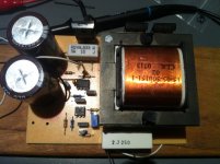
Open Source 1.5-2Kw Charger design

Yes, the UCC3802 - its the UCC3804's cousin, without a flip/flop on the output.

This is the upgraded IC from the UC3842/44. (current sense blanking (no need for an RC filter), gate pullup and zener internal to chip).

Once you pass 50% duty cycle you need slope compensation on the current loop, which is achieved by feeding the PWM ramp back into the current feedback pin (it is resistively summed). The UC3842 datasheet shows how to do this, the UCC3802 doesn't for some reason... :roll:

Since you are not sensing the current across the load (but the peak inductor current) some changes to the current limiting will have to be made. I'll build it and see how this all works with peak vs. average current.

I stole the modifed buck topology for an application note for a current mode LED driver chip, though it was very clever. The TL431 feedback is neccesary for the voltage feedback, otherwise an instrumentation amplifier would need to be used to reject the high common-mode voltages.
 
This is really a nice approach. I like the simplicity of the low side drive.

I would like to try a similar approach using a micro to drive the PWM, with the addition of current/voltage protection shutdown hardware so the micro could do no harm. I think a combined approach, with simple hardware to disable the micro if it screws up would solve many of the problems associated with an analog-only approach. The micro could even make some safety checks to insure proper ground isolation before applying charging current, and ramp the current up more gently, as well as control the soft-start relay.
 
I'm starting - sort of - to warm to the idea of the microcontroller. I probably wont go there with this design though.

I think they are too slow to respond to the current loop (voltage mode is fraught with difficulty for the same reason) as you need several cycles before they can respond to overcurrent. Hence my accumulation of dead power devices.

Ideally, you would use a current mode PWM controller for the current limiting, and use a microcontroller for feedback control of the voltage.

This design is a lot cheaper to implement, and probably a lot more robust than using 70's era PWM controllers (at least the UCC3804 was designed in 1999). In terms of the power electronics, its looking like about $20 worth of parts, even at farkenell prices.

I need to come up with a more universal inductor - I don't like (read I HATE) winding toroids, and high permeability E cores are cheap and readily available. Copper foil is cheap, as is mylar tape, so the excuse with having to find Litz wire isn't working.

As another aside - this design lends itself well to flyback converters - just thow another winding or two (bias and voltage feedback) on the core, and you have an isolated supply.
 
I was thinking of using a $1.00 micro to read voltage and current then set the PWM and just trip the FET/IGBT off if the voltage or current gets too high with hardware. Battery charging is low bandwidth, only if something goes wrong is fast needed. The micro can do nice smooth ramps. Trips should only occur on loose wires or software bugs.

In any case, proceed and good luck, great to see the experiments!
 
New version of the circuit onto a PCB.

New_Version.jpg

This PCB is about the same footprint as an Iphone :) The whole thing will be bigger obviously.

Current limiting works well, it passed the screwdriver across the output terminals test yesterday.

I'm not happy with the voltage regulation at the moment, but this is not a major issue, more to do with having insufficient bias on the TL431 I think.

Under low load (open circuit, 1K resistor across output @ 80V) - You can see the gate pulses keep the output at ~100% duty cycle.

View attachment 1

Under load - 250W


Some of the circuit values need revising as well, I messed up the frequency calculation somehow (ended up at a lower frequency than I wanted).
 
I'm in the "I have nothing to contribute but eagerly watch your progress" camp :p
A charger with an iphone-ish size footprint would be great for onboard charging, not only for e-motos like your vectrix but even many ebikes.
I'm about to start work on an madass conversion so something like this would be great for onboard plug in charging.

From your previous testing is it only at higher DC output voltages that the magic smoke starts to escape ?
If your previous/current revision is running happily at up to 150v that's a pretty respectable result in itself.
What charge voltage do you need for the vectrix ? Or are you just looking to make it as universal as possible with a wide voltage range ?
 
Hyena said:
I'm in the "I have nothing to contribute but eagerly watch your progress" camp :p
A charger with an iphone-ish size footprint would be great for onboard charging, not only for e-motos like your vectrix but even many ebikes.
I'm about to start work on an madass conversion so something like this would be great for onboard plug in charging.

From your previous testing is it only at higher DC output voltages that the magic smoke starts to escape ?
If your previous/current revision is running happily at up to 150v that's a pretty respectable result in itself.
What charge voltage do you need for the vectrix ? Or are you just looking to make it as universal as possible with a wide voltage range ?

The original design was stable to 155V @ 10A, but I was trying to push it higher (need 165V for 45 series lifepo4). I didn't like the stability of the current loop, it was 'conditionally stable' rather than a proper design which would be unconditionally stable. Power supplies and chargers that 'hiss' are verging on instability, this is why they blow. Once I pushed it to 190V the loop instability took out the Mosfet/IGBT - I could have 'Chinesed' the design and put two Mosfets in parallel, but a bandaid over a bad design is still that.

The footprint will be a bit larger, simply because of the requirement of common-mode filters on the input to stop interference making its way back to the mains. Buck topology utilises the inductor far more efficiently than push-pull or flyback, so smaller inductors are possible (especially with higher frequencies - 100Khz+)

I've managed to get the voltage stable-ish with the new design, I think I may revise it though, because rather than using the voltage feedback pin, I am using the shutdown pin, so it tends to be a bit brutal in terms of loop stability.

I also found an error in my PCB, TL431's produce an alarming amount of smoke when they shunt 120V :mrgreen:
 
More progress - I now have the current loop unconditionally stable - turns out that the UC3842 has an interesting flaw, its current sense input gets confused by a spike on turn-off that goes below zero volts. A shottky diode clamps that so it never happens.

Being a current mode controller, as soon as you pass 50% duty cycle, you end up with instability, and it oscillates at 1/2 the frequency - when you feed back the oscillator ramp into the current sense input via an emitter follower, it becomes unconditionally stable. And yes, that does include doing awful things like shorting its output.

The voltage loop is being a problem at low loads - I believe this is due to the optocoupler not being in a linear region - the CTR (current transfer ratio) of the opamp is only guaranteed for certain currents - when you are only switching 0.003mA, all bets are off. This has been causing a 5Khz subharmonic oscillation thats been driving me nuts trying to solve. It seems happy when it it loaded hard, but at low loads, the inductor hisses, and the oscilloscope shows a mess.

With a decent load (ie. 48V @ 350W) it is perfectly happy. I'm not moving to full scale testing till I get the voltage loop unconditionally stable. I reckon that I could probably get 2Kw out of it now without too much trouble, but the low load stuff isn't pretty.
 
Whilst thinking about the lowside buck topology, I considered how on earth someone would perform output voltage monitoring in a buck PFC - I remembered the UCC29910A (that I could never lay my hands on GRRR) and had a look through the datasheet.

Lo and behold - they use a level shifter (on page 10 - of http://www.ti.com/lit/ds/slusak8a/slusak8a.pdf) so I can toss the optocoupler and the TL431 that are proving to be a major PITA in my design, and monitor voltage directly. At least I can compensate normally with this design, and cull the parts count down even furthur (and not have optocoupler degradation, drift and failure to consider).

Isolation is not an issue, the output is unisolated, the opto was a cheat because I couldn't think of anything else to do the job.

Time for more parts, and a redesign of the PCB to incorporate this - fingers crossed.
 
Heath, how is the voltage and current set ? Simple pots ?
Not that it's terribly relevant from a bulk charging point of view as you'd pretty much set it for your application and that'd be it, but I'm thinking it could make a nice compact lab power supply too if the voltage and current can be easily adjusted
 
In a current mode converter, the voltage developed over the current sense resistor sets the current feedback loop - you could use a resistive divider to adjust this output.

The voltage mode is set using feedback resistors, the new version uses some trickery with a level shifter to change the differential voltage to a feedback voltage that the IC would normally expect - so, you should be able to use variable resistor in place of the fixed versions.

As for a lab supply - this is unisolated, so the outputs float at 175V DC in respect to earth. This is very bitey indeed. Potentially a free-running half or full-bridge wound 1:1 could be used to isolate the supply from the mains (much better (lighter) than an iron core isolation transformer). Use something like a IRS2153.

I would love to get this thing working with a PFC controller that lends itself well to this design - eg. NCP1651 the level shift for the vout will resolve the feedback issues here as well, and remove the opto. Single stage PFC unfortunatly requires a 1% 100Hz ripple on its output to perform the calcuations.

I'll design a PFC version when I get this one working nicely. Getting rid of that stupid optocoupler and TL431 out of the error amplifier will simplify things greatly for compensation. For something dirty like a battery charger, 1% ripple is tolerable.
 
A small update - the current mirror for the feedback section worked exactly as planned - no more optocouplers and TL431's (yay!).

Just simple type 1/2 compensation required now.

I've got to buy some bits at farnell again - stupid $45 for free shipping.
 
I just discoverede this great thread :D

Nice idea! i'm convinced that this will catch the interest of many members!

These TL494 and opto remember me some great souvenir when i designed my 2kW A/B class mono car audio amp and made the switching power supply section from scratch.. back in 1996 i used the IRFZ44... lol

A flexible cahrger for our wide voltage and current use!! GREAT !! 8)

One question: i saw that you have a power factor of 70.

do you plan on adding a PFC circuit to boost the efficiency?... and reduce apparent input power?

Doc
 
Interesting you used any feedback on a car audio amp - most people don't regulate simply because the rules used to specify output @ 12V (not ~14V). 2Kw with a voltage mode controller - urk. I used to use voltage mode a lot, but am playing around with current mode controllers (where the current loop is the inner and voltage is the outer control loop).

I used to do DB Drag racing years ago (which was fun but expensive and left me with permanent industrial deafness and tinnitus) - I discovered that the TL494 is also quite capable of being used as a Class D amplifier :)

The power factor is indeed pretty ordinary at 0.7. This is pretty much as good as it gets with a non-pfc SMPS unfortunatly.

I am meaning to utilise a power factor controller IC like the L6561 (which is a buck/boost/flyback topology) but at the moment, I'm working on getting it just plain stable.

Using a single stage PFC will result in some pretty serious output ripple, requiring a large capacitor bank and inductor on the output. Multi-stage is possible (ie. 400V rail from PFC, and then a buck stage).

Another thought is to use a large 48V PFC corrected supply as the base, and boost it up to the voltages that are required. The ESP120 3Kw supplies spring to mind as a contender.
 
Nice work heathyoung!
I know this is an old thread, but just wondering if heathyoung or anyone else has progressed with this open source design?
OR have you starte on another design that I haven't found yet

The reason I ask is that I smoked my ZEV charger yesterday and need to repair it or buy / build a replacement, for 28S LiFePO4 84V nominal and at least 10A output.
 
Back
Top