OpenSource Ampler

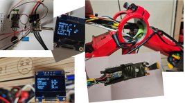
b) "Full Edition" - only once tested if it would fit. Wiring Harness might be little too thick. Technically its working.
- µC WEMOS D1 mini
- VESC mini 4.2
- Original Ampler Latching Switch / LED
- Light by BEC, digitally switched by WEMOS D1 mini via MOSFET. Blinking used as status feedback.
- Digital Communication µC to VESC
- Full Integration of Torque Sensor
- OLED Display as HMI

will be continued whenever the will be some free time...
Ampler Full.jpg
 
Spectacular work!
Myself have an Ampler Stout with a bad controller. But I chose the easier way, buying a generic KT controller and display.
The question I've run into now is, do I keep the torque sensor, or do I replace it with a generic pedal sensor.
I would like to keep the torque sensor, since it certantly is of better quality.
SBBRT -120L-1-8-708
But I have no way of connecting it, since the controller accepts a 3 wire PAS sensor, and the torque sensor has 5 wires.
Would you be able share a way to connect those 2?
 
Thanks a lot!

Guess you bought the SBBRT-120L-1-8-708 as replacement (I bought SBBRT-120L1-5-20 as replacement)
Originally there`s a SBBRT-120L-1-8-10 mounted to the ebike.

SBBRT-120-1-8-20 has 5 connection cables:
white VCC
black GND
grey Torque Singal (AnalogOut)
blue RPM Signal A
brown RPM Signal B

Did you find a manual online to check the pin-out of your sensor?

Surely your Controller will provide VCC + GND (pls measure Voltage level and check polarity) and expects pulses as input signal. Just pick up a Multimeter / Voltmeter and perform some quick measurements. Or check the manual of the KT controller.
Would use RPM Signal A for the 1st test.

Take care!
 
Last edited:
Actually tried that last evening.
Took the white and the black, and tried with the blue and then with brown one, but got nothing from the motor.
I suspect it's because the PAS sensor from the controller supplies 4.6V, and the documentation for the torque sensor says
Supply Voltage +7 … 16VDC.

So I'm not giving it enough voltage I believe.
I found this XL6009 DC-DC Boost Module that would allow me to give it the required voltage, but then, probably the returned voltage would be too high for the controller, so I would need some kind of resistance to lower the voltage again, but proportionaly somehow.
For ex: I raise the curent by 30% before the sensor, any output from the sensor would need to be reduced by 30%.
 
In my setup supply voltage is only 3.3VDC and PAS works fine. Torque won't work with voltages lower than 7VDC.

In your case I would advise the following
1) connect supply voltage and gnd to ncct sensor
2) connect voltmeter to gnd and rpmA
3) slowly turn the crank and check if you measure alternating high/low values depending on crank angle. If there's no change, check rpmB
4) note high and low values

5) connect standard PAS sensor instead of ncct and repeat the measurement
6) tell us about the result

Pictures might be helpful
 
Last edited:
Turns out my torque sensor is broken. No change in read voltage when pedalling. Will replace with a cadence sensor. Thanks for all the help.
 
Does anyone has the schematics for the rgb button that turns on the bike? Or at least the name.
I would like to reuse it (altough I would need something extra, since the button doesn't hold and i need a switch now) or buy something similar but the same size.
 
@graresf: keep us posted! Interested if your bike will be revived!

Back to the main topic: DIY Ampler Controller | Ampler Hack | Open Source Ampler

Did some improvements in the last days.

a)
Tuned the Controller Parameters. Wanted to realize a more smooth driving behaviour.
Parameters were optimized for a reduced "kick in" of motor torque.
Finally I generated a soft but noticable acceleration which should be more reliable in terms of wear.

-> Controller Parameter Tuning & Testdrive were absolutely successful (only used P I Paramters of Current Controller)
-> Driveability really nice

b)
Wanted to test how far I could push the limits: "Beast Mode" activated
Went up 13A maximum total Current. Added Field Weakening to increase torque at high rpm | high back EMF. Maximum 4A D-Current.
Have to admit: it`s a game changer! *annotation: only for use on private ground*
Motor, Battery and Controller feel quite cold after some rounds of testing, Brakes are close to or even above limit :)

-> Funny, but maybe not stable for long term use.
 
So you more or less doubled the power. Actually wondered if that would be sustainable.
My stout has an 8 something amps battery and the motor is AKM 100SX.
Mostly I'm worried about the battery, that it would catch fire or something. Dunno what kind of protections the BMS has.
The motor is rated 250w, but I guess it could get more without burning, if I pay attention to its temperature.

For how long did you use it on "Beast mode"?
 
Wow wel done!

I had the same thought about the torque sensor not working on a lower voltage. I never tried a higher voltage

Nice that you use an ESP32! I recently worked on some other project with a Wemos C3 Mini, it has Bluetooth making it perhaps easy to add some information and control via phone.

Very curios about the 13A mode ;) ;)
 
Did you add a 7V supply somehow for the torque sensor? Do you use the torque or just PAS?
 
So you more or less doubled the power. Actually wondered if that would be sustainable.
My stout has an 8 something amps battery and the motor is AKM 100SX.
Mostly I'm worried about the battery, that it would catch fire or something. Dunno what kind of protections the BMS has.
The motor is rated 250w, but I guess it could get more without burning, if I pay attention to its temperature.

For how long did you use it on "Beast mode"?

Long term tests are not yet carried out.

Power seems to be increased compared to original setup, but I think it´s not really doubled (we have to consider back emf, phase currents, ...)

My Ampler Battery has a 13s2p configuration using 26 3500mAh 18650 Cells.
Each is rated w/ 10A max discharge current (LG Cells).
So 20A max discharge current (2 cells in parallel) would be fine.

I replaced the BMS (old one was defective). New BMS is rated w/ 15A max discharge current.
So 13A max DC Current will be OK out of Battery and BMS perspective.

The Motor might be overloaded when driving uphill at low speeds for a long time.
We will see :)
Having fun is more important than a long lasting motor.
If it`s blown somewhen in time, it will be replaced with a higher rated component.
 
Wow wel done!

I had the same thought about the torque sensor not working on a lower voltage. I never tried a higher voltage

Nice that you use an ESP32! I recently worked on some other project with a Wemos C3 Mini, it has Bluetooth making it perhaps easy to add some information and control via phone.

Very curios about the 13A mode ;) ;)
Hi BB8 - thanks a lot for your feedback!
Higher Voltage is the key to activate the Torque Sensor.
Just used a DC-DC StepUp Converter.
7VDC is working well.
Disadvantage: you need additional space.
The Ampler Frame is really narrow...

Using WIFI or Bluetooth is a really nice idea. Maybe you will need an external antenna. The frame might be a very well working shield :)
 
Did you add a 7V supply somehow for the torque sensor? Do you use the torque or just PAS?
Pls check Post #25
Used an additional DC Step Up to add 7V Potential (same GND as WEMOS D1 mini) to supply the torque sensor.
Works quite well.
Used the analog input of WEMOS D1 mini + Resistor (to increase acceptable analog input range) to read out torque signal.

"Light Edition" only uses PAS (my current setup)
"Full Edition" used both PAS and Torque (not yet finished, but already working as prototype)
 
  • Like
Reactions: BB8
Long term tests are not yet carried out.

Power seems to be increased compared to original setup, but I think it´s not really doubled (we have to consider back emf, phase currents, ...)

My Ampler Battery has a 13s2p configuration using 26 3500mAh 18650 Cells.
Each is rated w/ 10A max discharge current (LG Cells).
So 20A max discharge current (2 cells in parallel) would be fine.

I replaced the BMS (old one was defective). New BMS is rated w/ 15A max discharge current.
So 13A max DC Current will be OK out of Battery and BMS perspective.

The Motor might be overloaded when driving uphill at low speeds for a long time.
We will see :)
Having fun is more important than a long lasting motor.
If it`s blown somewhen in time, it will be replaced with a higher rated component.
Thanks for the battery info. Not sure why I remembered it was a 8A battery, cause anything more than 13s2p would never fit in the package.

If the gods allow me (and my 3yo son) maybe I'll finish my bike and ride it in the weekend. I have everything ready, got the pas sensor the other day, just have to put things together.
 
  • Like
Reactions: BB8
Thanks for the battery info. Not sure why I remembered it was a 8A battery, cause anything more than 13s2p would never fit in the package.

If the gods allow me (and my 3yo son) maybe I'll finish my bike and ride it in the weekend. I have everything ready, got the pas sensor the other day, just have to put things together.

Keep us posted :)
 
Back
Top