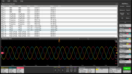
Hi, I'm new to ES. I'm working on a 3 phase BLDC Axial flux motor (12 Slots 14 Poles), recently used the oscilloscope to measure the voltage difference and the phase angle for the motor.
I used Isolated differential probes for the measurement, connecting the positive and negative terminals in different phase in a circular pattern.
I'm not a electrical engineer so don't have much knowledge on these field, Just learning for experimenting in the Lab. I want to know if the difference in the values are in limit with the industry standards.
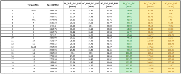
The image corresponds to motor rpm of 3825.
Looking for some help in understanding mor on how to design Axial flux motor and testing them.
I used Isolated differential probes for the measurement, connecting the positive and negative terminals in different phase in a circular pattern.
I'm not a electrical engineer so don't have much knowledge on these field, Just learning for experimenting in the Lab. I want to know if the difference in the values are in limit with the industry standards.
The image corresponds to motor rpm of 3825.
Looking for some help in understanding mor on how to design Axial flux motor and testing them.