Ping battery repair - I think my BMS is bad (now with pics)

Kevinator

100 W
Joined
Feb 2, 2010
Messages
145
Location
SoCal
I have a Ping 12v/15ah v2.5 that I use as a booster pack to go from 24v to 36v when the need arises. I didn't have any issues with this pack for several months but now I think there is a problem with the BMS.

I charged it up as usual, which means until all 4 leds are solid on the pack, and the led on the charger has finished cycling red/green and is a solid green. It currently measures:

14.22v at the charging and output wires coming from the BMS
14.33v at the battery pack (without BMS).

So there's a 0.11v loss through the BMS which may or not be normal as far as I know. The problem shows up when I apply a load. The voltage then measures:

3.22v at the output wires
14+v at the battery pack

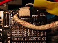
I unwrapped the pack and inside are 4x3-pouch cells, for a total of 12 pouches. Each cell measures:
3.54
3.54
3.58
3.54

Theres an oddball in there that seems to have a higher voltage whether standby or on the charger. Other than that, I believe my BMS is faulty. Is there anything I can do to test it and confirm?
 
I'm a dummy as ya'll know, but I don't understand what the problem is. It's not way out of balance, and fully charged. I don't know enough to say it's normal or not. Has capacity suffered or lvc not worked?
 
Capacity has been fine as far as I know. I ususally stop using the throttle when the amber light comes on indicating that i'm running out of battery.

I left my battery on the charger all day yesterday and it appears that balancing is working for the most part. It seems to balance way less than it used to (maybe 5-20 mins vs the 30min-several hrs as before), but all cells are showing 3.40v this morning. So the cells themselves appear ok. Measurement under load is currently 3.3v, so it looks like it follows the 0.1v drop through the BMS.

Keeping all that in mind, the numbers match up if I were to say that when underload, the BMS appears (my theory as a novice based on I don't know what) to only be passing voltage for 1 cell...3.3v instead of all 4 cells together which would be more like ~13.2v. Would this indicate that the BMS is shutting itself down? My limited knowledge is aware that a BMS will shut down a pack under heavy loads, but I don't know the techincal stuff behind it...like does it shut down individual cells, and you end up with a lower voltage figure on the output (3.3v in this case, possibly meaning the BMS is shutting down 3 cells and passing only 1 cell which would still trigger the LVC in your controller or throttle, which would stop the draw of power), or is it supposed to shut down the whole pack giving you 0v on the output.

I sent an email to PIng for help but I probably wont hear back until sunday night since its the weekend.
 
I have one of those and the pack is ok your charge is good but something is stopping 3 of your battries to not make it past the BMS. you probably need a new BMS. :mrgreen:
 
i agree with dogman, nothing wrong with it. maybe you can post up some pictures of what you are measuring so we could help you learn how they work. your pack has balanced so you know it is working, imo.
 
I apologize for the low quality pics. My camera sucks. Ok, here's pictures of the unwrapped 12v/15ah pack.

IMGA0404.JPG
View attachment IMGA0403.JPG
IMGA0400.JPG
View attachment IMGA0401.JPG


Here's my measurements at the pack (bypass bms)
View attachment diagram1.JPG

Here's what I am now using to draw a load
View attachment IMGA0405.JPG

When I plug the fan into this pack, nothing happens. The fan doesn't come on at all. Here's my measurements at the BMS when the fan is plugged in to draw a load
View attachment diagram2.JPG

Here's a picture of what a happy fan would look like, so theres no doubt about whether the fan is spinning or not. It will fire up just fine if I jump the negative wire directly to the pack (bypass bms).
IMGA0406.JPG
 
I agree with you guys, it looks like the pack is balancing fine. Its only the output that isn't working like normal. My Ping packs have always worked great, and this one specifically only has about 20 charges on it. I have been very happy with the weight and performance of these packs. I've been using it in series for a 36v/500w hub motor. None of the wires appear to be loose, or damaged. I do not see anything burnt on the board or anywhere else.

Is there any spots on the board itself I can check for voltages that would troubleshoot the low output voltage? I don't really know what's-what or the appropriate terminology, but I can use a multimeter and soldering iron.
 
HI KEVINATOR: have you been useing diodes when running in series like ping says? he say you need the diodes in series on each battery in order to protect the BMS and in parallel to keep one battery from chargeing the other battery. :mrgreen:
 
BLUESTREAK, I use diodes that I bought from Ping when I got my packs. :mrgreen: The diodes are rated for 100v/100a. There was a diode mounted to this pack before I removed it for troubleshooting, and to unwrap the pack.
 
dnmun said:
you have an 8S BMS. this is supposed to be a 12V pack?

yup, its a 12v pack. I had to email him to order it because he doesn't have 12v listed on his website.
 
why not just buy some more cells and make it a 24V pack since you already have the 8S BMS.

ping also has a 4S BMS, explain the situation, if he will sell you some more cells then you could make it into a 24V pack.
 
dnmun, you'll have to forgive my ignorance, but I'm not up to speed yet on what all the pack-building terminology is, such as 4s, 8s, 12s, etc. From what I gather, you're saying that once I get my BMS replaced, its possible to add 4 more cells to it. I wonder why I got an 8s, as opposed to a 4s in the first place (not that its a bad thing, other than possibly cost and size)? In any case, that would be awesome if this BMS will handle future expansion!

Yesterday I was wondering about what you're suggesting because I noticed that this BMS looked like it had room on the board to monitor another 4 cells. I currently have 3 Ping packs in 12v/15ah because it ended up being more practical for my situation as I plan on using them for more than just my ebike. They work excellent for running a netbook all weekend when you're out fishing or camping! That means movies, music, internet (sometimes), plenty of entertainment wherever you go. I read some have used these packs with their trolling motors, so I'm probably going to give that a shot too.
 
Im not sure but from those pics it looks that the output FETs are a different color than the balancer transistors... meaning they look like they are dirty or cooked from the pics.
-Mike
 
mwkeefer said:
Im not sure but from those pics it looks that the output FETs are a different color than the balancer transistors... meaning they look like they are dirty or cooked from the pics.
-Mike

I took a closer look and can't really tell if the fets look burnt, so here's some closeups:
IMGA0407.JPG
IMGA0410.JPG

That part of the BMS had blue plastic shrinkwrap around it, like the rest of the pack. Then the entire BMS is put into the clear plastic shrinkwrap. To be honest, I'm not sure what a cooked fet would look like. These fets do appear dirty, but upon closer inspection, it looks like either something rubbed across them leaving scuff marks. Or it had a very thin layer of paint (or something) that was partially rubbed off (possibly cooked off?).

Is there any way to confirm that the fets are bad? I poked around with my multimeter and go the following measurements. The 2.18v at the bottom of the list seems to stand out.
View attachment diagram3.JPG
 
in diagram 3, the 13.29 V should be 0V. it is connected to the negative terminal of the battery. that is ground. you should measure everything from that black wire. it goes directly to the bottom of the pack.

the leftmost leg on the FET is the gate. when it has 13V then the FET is turned on and when the voltage is 0V then the FET is turned off.

you have something wrong going on since the charging FET on the left side should be turned on so if it reads 2V then it implies it is off. but that is not possible since the cells are not at the high voltage cutoff limit. so i think that really should read 13V too.

i suspect you have everything backwards so start over and measure from the black wire where it says P-. put the black lead of your voltmeter there and measure everything. all the output FET gates are tied together so they will have the same voltage on the gate, that comes off the comparator chip, that 14 pin soic.

do all of your 12V packs have the same 8S BMS? 8S means 8 cells in series, 2P would mean 2 cells in parallel. how many sense wires go into the white plug?
 
dnmun, thanks for the transistor lessons! :D For my testing performed in diagram 3, the red lead from my voltmeter was placed on the red wires coming directly off the pack. The measurements came from placing the black lead from my voltmeter on each of the output FET legs.

Ok, here's the readings with the black lead on "P-", and the red lead on each of the FET legs.
View attachment diagram4.JPG
 
The white plug has 4 wires, so I assume its configured for 4s, but it looks like it wouldn't be hard to remove the plug and install one with 8 wires. The extra holes are already in the board, and as far as I know, it looks like it has 4 extra leds that it could use to monitor the new cells.
 

Attachments

  • IMGA0411.JPG
    IMGA0411.JPG
    69.8 KB · Views: 1,614
the charging FET is the one on the bottom. if you look on the back side you can see where the C- connects to the source leg of the charging FET. that connects the charger ground to the ground of the battery while the battery is charging. the drain leg is cut off and the tab is connected to the drain internally so the current flows into the source leg through the FET out to the pack through the drain which is the tab. the legs are gate, drain, source.

the other 4 FETs on top are the output FETs and they connect the ground from the controller to the battery through the shunt to the source legs and out the tab to the pack. you can see them on the back where the current flows into the source leg.

you should have 13V on the charging FET gate and 13V on the output FET gates.they should both be turned on since the voltage is not too high to shut off the charge and the output FETs should be on also since there is no low voltage that should cause it to be turned off.

it may be that the sense wires are not connected and you have a low voltage condition being detected since the cell is not connected to the BMS.

using the P- as your black probe spot, measure the voltage on each of the sense wires where the plug attaches to the pcb.

DO NOT short adjacent pins together on the sense wire plug by letting your red voltmeter probe contact 2 adjacent pins, contact only one pin at a time.

really, be careful doing this, a slip will burn up a sense wire at the least if you short them together.

that should tell you what is the input to the BMS comparator.
 
I don't know if this is normal, but I noticed that 2 of the legs of the charging fet were bridged with solder. I don't appear to be having an issue with charging, so maybe this normal...
View attachment diagram7.JPG
 
I had mentioned that Ping was going to replace the bad BMS under warranty. I decided to get another 12v/15ah battery pack, and some extra 12v BMS, and some extra diodes. They forgot to pack the charger and replacement BMS, but I sent an email to Ping and he got that cleared up quickly. Those items will be sent out on Mon.

I noticed that my new battery pack has a different BMS than what my old pack had. I asked Ping about that, and he said the new one is the latest v2.5 that has higher charging capacity and specifically made for 12v/4s. The old BMS was a v2.5 24v/8s that was modified for 12v/4s.

IMGA0474.JPG
IMGA0476.JPG
View attachment IMGA0477.JPG
 
Back
Top