docw009
1 MW
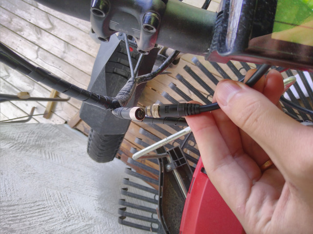
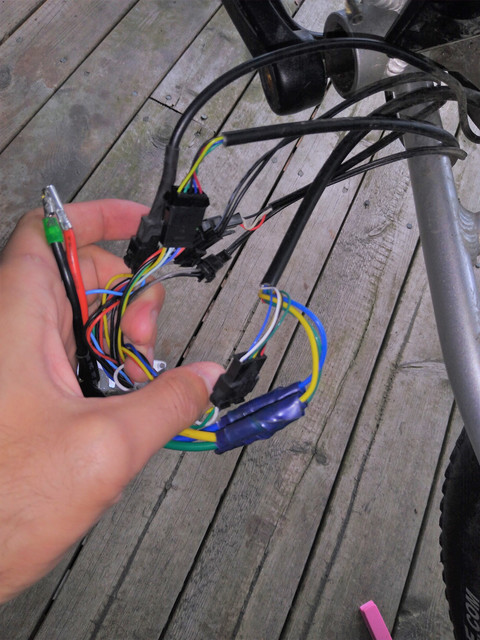
It's not a clear pic, but do your display, throttle, and brakes feed into a single harness? If so, trace the cable from the display til you get to a round connector. Unconnect it, and reseat it. First ebike we ever owned, had a dead display at the dealer. Tech called the importer, and was told to re-seat the connector. AFter I saw it working, I was dubious, but I wrote the check. Bike never had an issue afterwards.
l
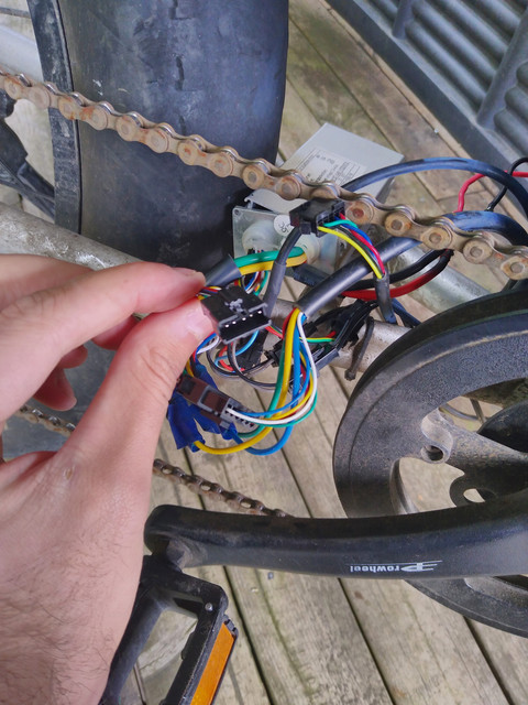
As for the controller, unless the top lid come off, don't try to disassemble it further. The little screws that fasten the transistor to the side of the case are what keeps you from sliding out the coircuit board. They're not easy to replace unless the top comes off.

l
As for the controller, unless the top lid come off, don't try to disassemble it further. The little screws that fasten the transistor to the side of the case are what keeps you from sliding out the coircuit board. They're not easy to replace unless the top comes off.