Possibility of putting 66V through an MXUS DD rear hub?

dnmun said:
there is no heat sink on your mosfets so you should be looking to buy a better controller anyway. those lipo shoulda already cooked that controller. kinda surprised to see it still intact.

There is a heat sink. This is one of those controllers where the FET tabs fit to a central heatsink bar in the case. If you look at the first photo in this thread you can see them fitted to a pretty substantial heatsink.
 
Ok, still unclear on the battery issue.
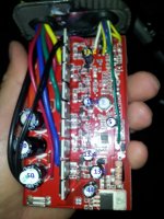
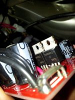
But had a closer look at the FETs and measured some voltages.
The smaller caps had voltage ranging from 5V to 44V. Pack voltage was 50V and as predicted all the larger caps measured 50V.
Photo detail:
cap_voltages.jpg
showing_fets.jpg

Am starting to think new controller time...
 
7.9mohm channel resistance


Page 1
Rev.1.00, September.26.2007, page 1 of 7 RJK0822SPN Silicon N Channel Power MOS FET Power Switching Rev.1.00 September.26.2007 Features • Low on-resistance R DS (on) = 7.9mΩ typ. (At V GS = 10V) • High speed switching • Low drive current • Suitable for motor drive, DC-DC converter, power switch and solenoid drive Outline Note: This product is designed for Electric Bike (E-Bike) application in China market.
Page 2
RJK0822SPN Rev.1.00, September.26.2007, page 2 of 7 Absolute Maximum Ratings (Ta = 25 ° C) Item Symbol Ratings Unit Drain to source voltage V DSS 80 V Gate to source voltage V GSS ± 20 V Drain current I D 80 A Drain peak current I D (pulse) Note1 320 A Body-drain diode reverse drain current I DR 80 A Channel dissipation Pch Note2 100 W Channel temperature Tch 150 ° C Storage temperature Tstg -55 To +150 ° C Notes: 1. PW ≤ 10 μs, duty cycle ≤ 1% 2. Tc = 25 ° C
 
In straightforward terms, that data sheet translates to "these FETs are fine at up to around 70V working voltage".........

Looks like all you need to do to run at over 62V or so is change the power supply resistor. If you want a belt and braces job to run at 66V, then change the resistor to one of 470 ohms, 3W and change the big capacitors to either 75V or 100V rated ones.

[edited to correct an error I made]
 
Thanks Jeremy

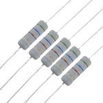
Something like this for the resistor replacement then:
http://www.ebay.co.uk/itm/10-Pcs-3W-500V-560-Ohm-Axial-Lead-Metal-Oxide-Film-Resistors-/130782404623
resistor.JPG

If I swapped out the resistor for one of these, would this affect performance at all? Apologies, obviously if I properly understood the science here I wouldn't need to ask this question.

That just leaves me wondering how to boost my current battery pack from 48V by using a couple more 2S lipos. Is this even possible if I want to re-use the 8 6S lipo bricks that I currently have? Would a diagram help? Is this something better asked in the battery technology section?
 
Those resistors look about right to me. It's certainly possible to add 2S packs (of the same capacity) in series to up the voltage, the key is to try and ensure all the paralleled sub-packs are of the same capacity (in Ah).

If I've understood correctly, you currently have 8 off 6S 4000mAh packs, wired as 4P, 2S sub-packs, giving you 12S at 16Ah. If you wanted to go to 14S, then you'd need 4off 2S 4000mAh packs wired as 4P again, giving you 14S at 16Ah. This should work fine, but may be a pain when it comes to charging.

14S is going to give you around 58.8V hot off charge and around 52 to 53V under normal discharge conditions. This should give you around 12 to 15% higher speed, as long as you're not running hard on the controller current limit at the moment.
 
Thanks again Jeremy.
I had feared as much re. the battery situation.
One possible solution is to add 2 of these then:
View attachment 1

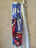
My battery case currently looks like this:
battery_case_8_lipos.jpg

So fitting them in could be tight. But it sounds like it would work. I would have to keep an eye on their discharge rates compared to the 6S bricks.

I got a reply from cellman re the stock controller that I have. I asked him if putting 14S through it would be ok. He said as long as I stay below 60V it should be ok.

So now wondering if I need to change the resistor at all?
 
The LM317 will definitely need a resistor change over 53-54V, so the max. you can run without modification is 13S lipo.
It can (and will) work for a while probably up to 15S, but risking this just to avoid an easy 5 minute solder job is silly.
 
You should be able to get away with using a couple of 8000Ah packs rather than four 4000Ah packs electrically, it'll just come down to whether they'll fit in your box, I think.

As miuan rightly says, I'm afraid Paul (cellman) is mistaken if he thinks that controller will be OK at much over 60V as it stands. The voltage regulator is an LM317K, which has an absolute maximum differential input voltage of 40V, so the max at its input would be around 52V. If the controller quiescent current is, say 50mA (0.05A, which is pretty typical) and as the resistor in there at the moment is 180 ohms, that means that the resistor will drop 180ohms x 0.05A = 9V. The max input voltage would then be 52V + 9V = 61V or so, higher than that risks cooking the regulator.

You can double check to see if the current I've used above is correct, by measuring the current the controller draws with everything connected but the throttle off. If the current is greater than 50mA, then the voltage drop across that 180 ohm resistor will also be greater. The calculation to get the voltage drop across the resistor is resistor value (in ohms) x quiescent current (in amps). This was pretty well documented here when folk first started modding controllers. Knuckles did some (fairly crude, it has to be said!) work on getting controllers to run reliably at higher voltages and wrote it up here: http://endless-sphere.com/forums/viewtopic.php?f=16&t=7361 (that thread relates to the old Infineon controllers, but they use exactly the same power supply as your controller).

[edited to correct an error on my part, as pointed out below by miuan]
 
Jeremy, I thought the LM317 had 60V max. input and 40V max. difference.
If what you indicate is true (40V max input), then it's already been overvolted by 4V now (at 12S) since the input cap shows 44V.
 
miuan said:
Jeremy, I thought the LM317 had 60V max. input and 40V max. difference.
If what you indicate is true (40V max input), then it's already been overvolted by 4V now (at 12S) since the input cap shows 44V.

Whoops, my bad! Thanks for pointing that out.

You're right about the differential being 40V, except that I can't see a max input voltage rating on the datasheets I have (and looking at how it works internally I don't think the regulator really cares about anything but the differential voltage). That means the regulator is OK for 52V input maximum when set for 12V, which is pretty typical for most controllers. Add in the 9V from the 180 ohm resistor drop (assuming the current is 50mA) and it then looks as if 60V is just about OK, but anything over 61V is pushing it.
 
Thanks.

So basically with a resistor mod I won't have to buy a new controller to jump from 12S to 14S.
I now need to work out which option to take.

Option 1: Go 14S with a couple of 8Ah zippys
Option 2: Go 18S with one new 4Ah turnigy and buy a new controller.

The 14S option is slightly cheaper and would restrict my max speed to a safe(r) 28mph or so. But the different battery bricks cause minor inconvenience with their different discharge leads (yes I could swap these), but also I'd have to watch them more closely than if I got one more of the same brick.

The 18S option is probably simpler and 'cleaner'. I would probably go for a cellman recommended IRFB4110 25A controller which is designed for up to 72V. Theoretical top speed around 36mph (I would *not* feel safe at this speed, never mind the impossibility of pedaling).

Will think on it. Any opinions gratefully received.
 
monkeychops said:
Option 1: Go 14S with a couple of 8Ah zippys
Option 2: Go 18S with one new 4Ah turnigy and buy a new controller.

Don't buy Zippies. They are not quite the rated capacity or discharge rate of the Turnigys you already have. You'd end up with a battery where 2 cells out of 14 are capacity bottleneck, and no way of determining a safe low voltage cutoff level for whole pack without leaving too much capacity reserve in the Turnigys, or monitoring the 2S packs - which would introduce a fair share of issues. If you have to go the 2S route, go with the same kind of cells you have now, so you have a well matched pack that you can rely on.

monkeychops said:
The 18S option is probably simpler and 'cleaner'. I would probably go for a cellman recommended IRFB4110 25A controller which is designed for up to 72V. Theoretical top speed around 36mph (I would *not* feel safe at this speed, never mind the impossibility of pedaling).

You can still limit your speed to whatever value (1 to 100% of full speed) by programming the controller and/or using a 3-speed switch. Ask cellman to include a programming cable for a small surcharge, or even do the programming for you, it's an under 5 minute job for an experienced user like him. Then later, when (rather than if, lol) you feel more need for speed, you just increase the speed and look for a gearing upgrade to be able to pedal at 35mph (a 48/11 ratio is enough for that).

Edit: You can limit speed even without programming. I have repeatedly used a diode or two in series with the green (output signal) throttle wire, effectively dropping the output voltage of throttle and thus lowering max. speed. Very easy to set up and break up if you ever need to.
 
Thanks for your reply miuan. I think I've read that about the Zippys, now you mention it. I guess I could get 4 x 4Ah 2S Turnigys but it's more cells to check on, more wires...

It's looking more like the 18S option then probably. I haven't heard of (m)any people mixing up packs like I have considered doing here.

So new controller time. Cellman offers an upgraded controller that's not necessarily cheaper than eBay but not much more $. He has a 3 speed switch too. Other sellers are available of course, but his customer service has been excellent.

One outstanding question remains about the bulk charging option. I am using a Meanwell clone at the moment. But it maxes out at 53V (when I turn the adjusting dial fully to the right). Does anyone know if they can be easily modded up to more like 72V? Or is it better to buy one rated at 72V?
 
monkeychops said:
I haven't heard of (m)any people mixing up packs like I have considered doing here.

I've done that. Turnigy and Zippy 20C. The Zippies, although almost a year newer than Turnigy, sag more and get to LVC sooner. It's a mini pack from extra packs that I had, for nearby pub and shopping errands, so I don't care too much anyway... but I'd never want it as a main pack. Maybe 8.5-9Ah of 30C Zippy would better equal 8Ah of 20C Turnigy, but that's just guessing.

monkeychops said:
One outstanding question remains about the bulk charging option. I am using a Meanwell clone at the moment. But it maxes out at 53V (when I turn the adjusting dial fully to the right). Does anyone know if they can be easily modded up to more like 72V? Or is it better to buy one rated at 72V?

I am afraid you are screwed with the Meanwell. You need something like this set to 75V:
http://www.greenbikekit.com/index.php/battery-charger/360w.html
 
true 72V DC or 72V nominal? you can use a kingpan charger in series with the meanwell and then use the charger to limit the current. i did that for a 22S pack i built. used a meanwell clone set to 52 and the 24V kingpan set to 28.4 to get 80.4V.

i also hacked the charger shunt to make the charger push 7A so i could use the full power of both. so it is now 80.4V charger at 7A about 560W. works great.
 
Maybe one solution to the charging issue is to wire up the battery packs with some clever splitting harness arrangement so that I can charge at 48V still. Maybe use some 'Y' harnesses <edit>of course, like a reverse parallel harness!</edit> on the 3 paralleled 6S sets to combine them differently for charging.
I bet some people must have done this.
They don't seem to make Meanwell clones higher than 60V :-(
Maybe this is another reason to stick to the 14S solution.
 
dnmun said:
true 72V DC or 72V nominal? you can use a kingpan charger in series with the meanwell and then use the charger to limit the current. i did that for a 22S pack i built. used a meanwell clone set to 52 and the 24V kingpan set to 28.4 to get 80.4V.

At the moment I'm charging at work, with an old (but innocent looking) SLA charger, which runs at 100W. It's slow, but quiet, and also means I can leave the charger in my drawer and use my meanwell clone at home. Don't really like the idea of having to use 2 chargers in series.
 
Thinking about it, is it even going to be possible to wire up 9 x 6S lipos for bulk charging using a 48V Meanwell clone?

If I put 4 of them in parallel and the other 5 also in parallel and then series the 2 sets together, would charging happen evenly, given that the parallel sets are an uneven number? It doesn't seem like it would work. It makes my head hurt trying to work it out.
 
Jeremy Harris said:
Take a look inside the controller first, as it's probable that the commutation capacitors may only be rated to 63V and also that the FETs may not be rated for much over 60V. If you can post the FET part numbers printed on the black plastic bit then it's easy to check to see what they'll take. The capacitor absolute maximum voltage will be printed on the can, the capacitors in question will be the largest ones inside the controller; some of the smaller ones will be working at a lower voltage as they'll be on one or more of the low voltage supply rails in the controller.
hm,
my capacitors 63V, but I used 67.2V many time, its ok.
 
iperov said:
hm,
my capacitors 63V, but I used 67.2V many time, its ok.

Good for you, you got very lucky. Next time they may just go bang on you. If you don't believe me, put a capacitor on a power supply, turn it up to a voltage above the rating and wait. Before long it will blow the top out. Before they added the little weak spot on the cans (the cross pressed into the top) they would blow the cans off like bullets. It used to be a favourite trick in the lab, as there was no telling how long they'd take to blow, could be a few hours before they went and would catch people by surprise.

All of the reliability testing that's been done over many years, all over the globe has proved, beyond any doubt, that even running at close the maximum rated voltage reduces reliability.
 
Is any 63V cap designed specifically to be 63V? Or did they simply fail the test for (say) 80V? A bit like speed ratings for computer processors.

I'm not advocating running over their voltage rating, but it might explain why some caps might take a little extra and others not.
 
Punx0r said:
Is any 63V cap designed specifically to be 63V? Or did they simply fail the test for (say) 80V? A bit like speed ratings for computer processors.

I'm not advocating running over their voltage rating, but it might explain why some caps might take a little extra and others not.

They are physically designed for the voltage, which is why higher voltage capacitors of the same capacitance are physically larger. The voltage rating is actually the electrical breakdown point of the very, very thin insulation layer between the plates. In the case of an electrolytic capacitor this layer is a very thin oxide layer on an aluminium plate (the liquid electrolyte forms the other plate), so it is susceptible to failure, often in small regions at first. The first indication of failure is that the DC leakage current will gradually increase, heating the capacitor up locally and eventually causing it to over-pressurise (from the electrolyte vaporising) and then fail.

Even if not abused the capacitors will fail from old age, as electrolytic capacitors suffer from a limited life, even if run within their ratings. The electrolyte dries out, so the warmer they are run the shorter their life.
 
Sorry, just to recap because I'm now thinking of an upgrade to 15S.
I charge to 4.1V per cell so this will give me a maximum of 61.5V.
But my pack sags about 1V under full load, so this will be a maximum of 60.5V going into the controller under power.
Is that likely to be ok without any modifications to the controller?
I know the resistor mod was mentioned but I'm kind of reluctant to do this now, for reasons of my own incompetence.
 
Back
Top