Possibility of putting 66V through an MXUS DD rear hub?

It's your call. People here have run controllers right at the edge like this and had them survive, but others have found that they've just failed. It is normal in the electronics industry to derate components for reliability, as has been discussed here several times before. Bigmoose posted a useful industry standard derating guide at the end of this topic: http://endless-sphere.com/forums/viewtopic.php?f=2&t=40264&p=588561
 
Running 15S RC Lipo 2-3 years on stock Infineon controllers with 63V caps. My normal hot voltage is about 62V and haven't had any problems yet. That doesn't mean everybody will get away with it but it's worked for me on a daily basis.

Of course, I keep a spare controller on hand so even with a failure I won't be sitting dead for days/weeks.
 
Ok, thanks Jeremy.
<edit>thanks Ykick too</edit>

Just to be absolutely clear for an old duffer like me:

1. Replacing that resistor with a 3W, 560 Ohm one like this http://www.ebay.co.uk/itm/10-Pcs-3W-500V-560-Ohm-Axial-Lead-Metal-Oxide-Film-Resistors-/130782404623 will significantly reduce the risk of a capacitor blowing when connected to a 61.5V battery.

2. I can literally just swap out the resistor with one of those. There is no 'wrong way round' with connecting a resistor like this in series?

3. Using my multimeter as I have done above to measure the V drop across the caps, will I be able to observe a difference in measured voltage across any of them?

4. Lastly, will there be any sort of performance hit with replacing this resistor like this?
 
monkeychops said:
Ok, thanks Jeremy.

Just to be absolutely clear for an old duffer like me:

1. Replacing that resistor with a 3W, 560 Ohm one like this http://www.ebay.co.uk/itm/10-Pcs-3W-500V-560-Ohm-Axial-Lead-Metal-Oxide-Film-Resistors-/130782404623 will significantly reduce the risk of a capacitor blowing when connected to a 61.5V battery.

2. I can literally just swap out the resistor with one of those. There is no 'wrong way round' with connecting a resistor like this in series?

3. Using my multimeter as I have done above to measure the V drop across the caps, will I be able to observe a difference in measured voltage across any of them?

4. Lastly, will there be any sort of performance hit with replacing this resistor like this?

Changing the regulator resistor won't have any effect on the main capacitor voltage at all, as this is just a way of keeping the voltage regulator inside its maximum rating. The voltage regulator feeds the low voltage parts of the circuit and has a maximum rating of 40V (the difference in voltage between its output voltage (around 11 to 13V normally) and its input voltage (the battery voltage). Before swapping it, best check the current that the controller draws with the throttle and motor Halls connected but without the throttle being operated. It should be around 50mA, but if it is much different than this then the resistor value may need to be different (I think we mentioned this earlier in this thread). The resistor can go anyway around. Changing the power supply resistor has no effect on the controller other than keeping internal things working within limits.

The main capacitors always see the full battery voltage plus the ripple voltage from the switching process that runs the motor (so in practice they will see a volt or two over the battery voltage when there is a fair bit of ripple, such as at high torque loads on the motor at fairly low speeds). That thread I linked to gives a pretty good run down on the pros and cons of running controller capacitors at, or close to, their absolute maximum voltage rating.
 
Jeremy Harris said:
Before swapping it, best check the current that the controller draws with the throttle and motor Halls connected but without the throttle being operated. It should be around 50mA, but if it is much different than this then the resistor value may need to be different.

I'm not confident measuring current. I have a multimeter that does it, but you have to break the circuit don't you? From one of the photos on page 2 of this thread, can you tell me where the 2 probes would have to connect? Or is it not that simple. Sorry to be such a noob. Feel free to draw a line under this if you get fed up.
 
you use the ammeter portion of your voltmeter. there is a scale that says 200mA so set it to that. use only the small red wire that goes to the controller, you don't even have to connect the large red wire.

measure the current flowing into the controller on that small red wire. that is the controller circuit current. it should be about 50-65mA. if you have 61V on the pack, 180ohms X .050A = 9V voltage drop across the resistor. so the voltage regulator sees 52V on the input of the regulator. it has to make 12V come out the bottom and the limit of how much it can drop the voltage is about 40V max so your 12V rail will just barely be able to stay down at 12V. it will most likely be about 15V and the regulator will be maxed out and trying to burn up as it keeps the 12V rail at 15V. but it will still work. the transistors that get power from the 12V rail will work up to about 21V.

if you change the 180 ohm resistor to 470ohm, another common value, the voltage drop is about 23V so the voltage regulator has 39V on the input and it can hold the 12V rail down at 12V without too much heat.

make sense what he is talking? so both the caps and the voltage regulator will be working at the limits of what they can do. but they will do it. until they fail. then you can fix it.
 
Oh hang on, are you talking about the current coming into the controller direct from the battery?

Not the current in some internal bit of the controller circuit?

So, with the controller fully connected up, disconnect the +ve battery supply connector and connect the tips of my multimeter in series with this connection break? i.e. one tip on each of the disconnected wires. Obviously with the multimeter in amps mode.

Ok, re-reading the posts above it looks like that's what you mean. I'll do that tonight. No need to open up the controller again then.

Sorry for being thick here.
 
monkeychops said:
Oh hang on, are you talking about the current coming into the controller direct from the battery?

Not the current in some internal bit of the controller circuit?

So, with the controller fully connected up, disconnect the +ve battery supply connector and connect the tips of my multimeter in series with this connection break? i.e. one tip on each of the disconnected wires. Obviously with the multimeter in amps mode.

Ok, re-reading the posts above it looks like that's what you mean. I'll do that tonight. No need to open up the controller again then.

Sorry for being thick here.

Yes, that's right. Just a quick word of caution if you do it that way, though. The controller capacitors charge up when power is first applied, and draw a high current for a fraction of a second. Probably not enough to damage the meter, but it might blow the low current fuse in the meter of you do this with it in the 200mA range.

The fix is easy:

1. If your meter has only one set of current measurement terminals then just set the meter to the highest current range at first and then turn it down to the 200mA range a second or two after power on.

2. If your meter has a separate high current connection, then use the low current connection but use a short bit of wire (pretty much anything handy will do) to short the meter terminals whilst you hook the probes up. A second or two after hooking it up you can remove the shorting link and read the current on the meter.

If you can get at the controller "ignition" wire, usually the thin red wire as dnmun rightly suggested above, then it's better to make the measurement there, as there will be no capacitor charge inrush current at that point, just the low current that the controller draws.
 
yeh, yeh, i never thought you might not have a separate small red wire. if you don't it is a hassle like he said, and there maybe is a little drain down resistor on the caps too that add to the current. i should look at the picture of your controller. here somewhere.

edit, ok looks like you do not have a separate small red wire for the circuit current so that won't work. but i think 50mA is a minimum for the circuit and maybe is 65-80mA so don't stress. but if you can find a 2-3W resistor to add to that one to get to the 500 ohm range it would be worth doing, imo. otherwise don't sweat it too much now.
 
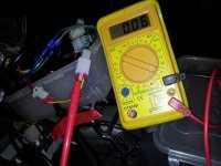
I found an ignition wire and measured the current though it.
Unfortunately my multimeter isn't that precise. Looks like around 60mA though:

20121023_200229.jpg

Remind me where that leaves me? This was the missing information from the equation to get the right resistance for the larger resistor? Which we are still saying is required?
 
ok, that is it. i saw that green wire and thought maybe but wasn't sure. but i guess i kinda recognize you won't have a soldering iron and some 60/40 solder even if you find the power resistor. so just go with it like this and if it blows up later, deal with it then.
 
OK, 60mA means that the 180 ohm resistor that's in there at the moment (the big one with the brown - grey - brown stripes) is dropping 180 x 0.06 = 10.6V. The regulator will be delivering around 12 to 13V, and has a maximum permitted voltage across it of 40V, so that means that, to be safe, the resistor value needs to be increased so that it can drop at least 62V - 40V - 12V = 10V, which is right on the edge for that 180ohm resistor.

To give things a safe margin, then the resistor needs to drop around 20V at 60mA, which means it needs to have a value of around 20 / 0.06 = 333 ohms. The closest preferred value resistor to this is 330 ohm, which will be fine.

The power rating that the resistor will need is given by the voltage dropped across it, about 20V, multiplied by the current flowing through it, 0.06A. 20 x 0.06 = 1.2W. A 2W resistor should be fine.

So, if you change the 180 ohm resistor one for a similar size 330 ohm, 2W, one then that should be near-perfect.
 
Get a new controller. Overbuilding is always better, because Murphys law will cause the stock controller, ran at the limit, to blow right at the point you are furthest away from home. The overall system will run more efficient also when well within spec, and not at the limit. Do it once, do it right. That's my 2 cents.
 
monkeychops said:
Thanks. Will get one of these and report back later.
http://www.ebay.co.uk/itm/5x-330-ohm-330R-2W-2-Watt-Metal-Film-Resistor-/170681466367

i can mail you a 200 or 300 ohm resistor if you can't find one locally. you don't actually need 2W either. the 180 ohm resistor dissipates only .65W. so if you can find a 1W resistor in the range of 150-250 ohms you can solder it in series with that one to get a total resistance in the 400-500 ohm range like he said. do they have radio shack there or similar electronics suppliers? they will have a small power resistor for you in that range. if you add one over about 250 ohms you should go to 2W though.

you add a resistor in series by unsoldering one leg of that one, pulling the leg outa the through hole, and standing the resistor up and soldering the second resistor to the high leg and the other leg goes down into the empty through hole where you solder it down.
 
Looking at the photos I'm not sure there's room in that case to stand the resistors up on end. As the OP is here in the UK, getting one from ebay and replacing it may well be the easiest option. The closest we have here to the hobby electronics shops in the US is Maplin's, although they only keep a limited stock of components and they may not have a shop near to where the OP lives (although he may not be far from me, and there is a Maplin store in Salisbury).
 
i find it is cheaper to have stuff delivered by mail from hong kong than drive the 30 miles round trip to the electronics shop on the other side of town. but now that place went under too.

this is where i buy resistors and stuff: cheap cheap with no shipping charge, nice guy, sells a mix of resistors too:

http://stores.ebay.com/CENTRUY-SOURCES-H-K-LIMITED?_rdc=1
 
I've asked cellman for a new controller.

Put the controller back together the other night. All seemed fine, the wheel turned when I tested it in the garage.

Started cycling to work this morning. Grinding sound straight away then complete loss of power.

When I reassembled the controller I couldn't get the heat sink bar in without removing a strip of white gluey tape. So now I'm thinking I've shorted something. Maybe. Fed up.

After sitting on the bus pondering things for most of the 50 minute journey, I caved in and emailed cellman for a new controller. Then had a quick game of Fifa soccer on my phone and tried to forget all my failures in all things electrical and mechanical.
 
Update:

Possibly slightly over-reacted in my previous post. I have calmed down now.

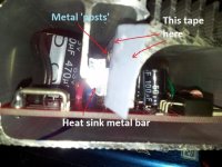
Got home and opened the controller up and reassembled with piece of thin tape insulating the metal 'posts' that the FETs sit on.

You can just see the grey/white original tape in this photo:
20121017_211729.jpg

It's sticking out towards the camera and sits between the controller case and the metal 'posts'.
I put a bit of thin cellotape there instead. Anything thicker and it just wasn't possible to slide the board back into the controller case without the tape bunching up like a loose piece of carpet or rug.

So anyway, all seems fine now. Went for a quick 2km test ride just now.

I've postponed the new cellman controller and for now I'm putting plan 'A' into operation. The resistors have arrived and I will be replacing mine soon.

Anyone know whether that tape I'm referring to is significant? It certainly appeared to be from what happened to me, but good to be sure.
 
Yes, the tape is critical! It's the only insulator between the FETs and the heatsink, and if it fails the FETs will short to the case, often with lots of smoke (the FET tabs are electrically connected to one of the FET terminals internally). You seem to have got lucky and only had a short that caused a glitch, rather than a smoking ruin, which is great. The tape I use instead of the grey silicone pads is Kapton insulating tape, as it's thin, has good insulating properties and is a fairly good conductor of heat.

My advice would be to get some Kapton tape and replace the cellotape with it, as I suspect the cellotape will fail at some point. You should also put a thin smear of conductive grease on it (the white stuff you're probably already encountered in there) to aid thermal contact.
 
Hi guys.

I've soldered in a new resistor as suggested and measured the voltages across all the capacitors again in the same way as before.
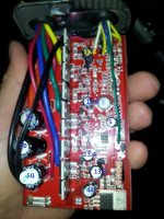
Previously the voltages measured as per this photo:

cap_voltages.jpg

The only one significantly different with the new resistor is the one at the bottom of the pic, previously measuring 44V. This is now at 38.3V. I think this is in line with expectations. The larger capacitors are 0.5V down, but I think this is due to my total battery voltage being 0.5V down this time (total pack votage = 49.4V this time).

So with the impending upgrade to 15S with total pack voltage at 61.5V (each cell charged to 4.1V), the controller should now be hunky-dory I think?

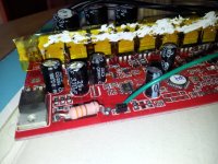
<edit>Photo showing new resistor, Kapton tape and thermal grease.
20121103_140528.jpg
</edit>
 
dnmun said:
what is the voltage on the 12V rail?

Not sure. The voltages are as indicated on the photo above, except for the one measuring 44V which now measures 38.3V.
Tell me what I should measure and I'm there, multimeter in hand!

<edit>Resistance of the new resistor rated at 330 ohms and measured by me just now with multimeter at 340 ohms.</edit>
 
Back
Top