
tef
1 W
hi,
I hope that somebody can help me with troubleshooting my 3kw brushless scooter hub motor.
The third controller is still not working.
the story:
This summer I bought a used scooter with 60V lead acid batteries.
The original controller let the hub spin but the speed was less than 10km/h up the hill.
I did not test further because my A123 cells were on the way and I had to remove the slas and upgrade the original infineon controller for higher voltage (fets, caps,...).
The modified controller shorted after a few metres.
I thought that something went wrong with the controller upgrade (fets not properly isolated,...) and replaced the defective fets and rechecked everything.
But the controller shorted immediately after just "touching" the throttle.
The Hall sensors were switching between 0 and 5V and I could not detect shorts between the phases of the motor (resistance is equal (200mOhm), no suspicious cogging).
After spending days with modifying and repairing, I decided to give up with this controller and ordered a new 24fet 4110 from lyen.
I found the correct hall/phase combination and tested with very conservative current settings.
Result of test under load: shorted mosfets
I thought that the low resistance or inducance of the motor is a problem for those infineon controllers and ordered a Kelly KBL09401B.
I went through all 36 hall/phase combinations a couple of times with 60 and 120 degrees hall spacing.
There is no combination which lets the 13'' motor spin faster than a few rpm.
If I get the motor to spin, it sounds rough and the controller starts to report a hall error after some turns.
At that time the halls were still ok.
Afterwards I managed Somehow to damage the halls during trial and error hall/phase matching, so I opened the motor and replaced them successfully with honeywell ss41.
I even rewired everything and upgraded the phase wires, but no change. The motor just turns slowly and sounds rough as before.
BTW, the middle of the three halls is reversed!! I read somewhere that this is an indicator for a 60 deg hall placement?
There is a position where all three sensors put out 5V!
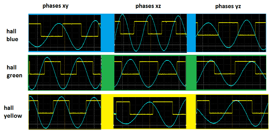
The last thing I did is to attach a scope and measured the back EMF voltages together with the hall signals.
I labeled the phases x,y and z and attached one scope channel to the halls and one to the phases.
The wheel was turned backwards.
I just know the basics of EE and don't know how to go on.
Can somebody please tell me if there is something suspicious (placement of hall sensors)?
I attached a screenshot of the measurements and pictures of the stator with the halls.


tef
I hope that somebody can help me with troubleshooting my 3kw brushless scooter hub motor.
The third controller is still not working.
the story:
This summer I bought a used scooter with 60V lead acid batteries.
The original controller let the hub spin but the speed was less than 10km/h up the hill.
I did not test further because my A123 cells were on the way and I had to remove the slas and upgrade the original infineon controller for higher voltage (fets, caps,...).
The modified controller shorted after a few metres.
I thought that something went wrong with the controller upgrade (fets not properly isolated,...) and replaced the defective fets and rechecked everything.
But the controller shorted immediately after just "touching" the throttle.
The Hall sensors were switching between 0 and 5V and I could not detect shorts between the phases of the motor (resistance is equal (200mOhm), no suspicious cogging).
After spending days with modifying and repairing, I decided to give up with this controller and ordered a new 24fet 4110 from lyen.
I found the correct hall/phase combination and tested with very conservative current settings.
Result of test under load: shorted mosfets
I thought that the low resistance or inducance of the motor is a problem for those infineon controllers and ordered a Kelly KBL09401B.
I went through all 36 hall/phase combinations a couple of times with 60 and 120 degrees hall spacing.
There is no combination which lets the 13'' motor spin faster than a few rpm.
If I get the motor to spin, it sounds rough and the controller starts to report a hall error after some turns.
At that time the halls were still ok.
Afterwards I managed Somehow to damage the halls during trial and error hall/phase matching, so I opened the motor and replaced them successfully with honeywell ss41.
I even rewired everything and upgraded the phase wires, but no change. The motor just turns slowly and sounds rough as before.
BTW, the middle of the three halls is reversed!! I read somewhere that this is an indicator for a 60 deg hall placement?
There is a position where all three sensors put out 5V!
The last thing I did is to attach a scope and measured the back EMF voltages together with the hall signals.
I labeled the phases x,y and z and attached one scope channel to the halls and one to the phases.
The wheel was turned backwards.
I just know the basics of EE and don't know how to go on.
Can somebody please tell me if there is something suspicious (placement of hall sensors)?
I attached a screenshot of the measurements and pictures of the stator with the halls.
tef
 .
.