So over the next few years I hope to complete this project. This'll be my build thread. Should be fun and full of trials and tribulations, but I have a plan to streamline parts of the process and I have a good idea of how everything will fit together. Any input is definitely welcome, this idea has been going under mental revision for at least a year now.
I love my KMX/A123/Cro/Max-E build but I want something that's more comfortable, weatherproof, and has more storage. Then it'll be perfect...
My goals? Minimal maintenance, maximum comfort, maximum versatility, uncompromising performance. Too good to be true? I hope we find out! It'll have a Cro, Max-E, serial-hybrid drivetrain-- that is, regenning BB with a PAS, a seat that is either recumbent or pops up with the handlebars for motorcycle-like straddling that should even accommodate extra passengers, zero point-turn radius, awesome full-suspension all around, a geometric and possibly an additional pneumatic damping system to limit rapid tilting for safety in low-traction conditions. Oh yes, and I think I will get 800x Samsung SDI 25R cells, 2.5ah and "10c" rated, overblown number but they can manage 1c rapid charge and if the whole pack can discharge 80,000+ watts peak in ideal conditions, I think I can expect passable performance in the winter. With a 1-hour charge on a 200-300 mile pack, I should be able to ride across the country. Not to mention that I'll still be able to charge overnight off of 110v if I have to stop somewhere and they don't have J1772/NEMA 14-50.
I'll achieve these points with the following design elements:
Vertical leading link fork. This will facilitate several things-- firstly, its a good design for a suspended FWD hubmotor, very sturdy. Second, the geometry works well for zero-point turns, which will remain ergonomic via simple U-joint linkage. This linkage will also allow easy adjustment of handlebar height, which will facilitate yet another point; the back of my seat will be able to flip up near the headrest and lock up, so that I can ride upright if I want. At least part of the fairing will be attached to the handlebars, and raise with it. There will be doors, which will both move forward on the inside of the fairing
Short wheelbase. The front wheel will be vertically in line with my knees in a reclined position, this will increase load on the front and help with traction. This will also help in slippery conditions, and make those aforementioned zero-point turns quite negotiable. I plan on regen-braking a lot but I'm looking at getting a moto hydraulic brake and disc on my Cro... alternatively, some DH brakes should do.
Self-centering geometry. The rear swingarms will be designed such that leaning will increase the overall center of gravity as it moves from the midline, instead of lowering it like a traditional linear track vehicle. It probably won't be enough to reliably remain upright at a stop, I'll have a lean-lock for that, but it'll help dampen excessive leaning due to loss of rear traction (which should never occur anyway in a FWD setup-- if you can tell, I plan on riding in snow and ice) Furthermore, It'll be very easy to weld up spare, xtra-wide swingarms if I decide i need more track in the winter.
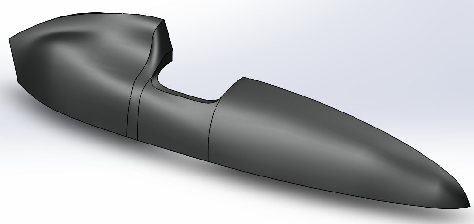
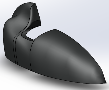
Full fairing with a bubble. I want to be able to hunker down and cut through the wind. I don't want to blink when I think about riding in -20F weather. Or 100F weather, I've already designed some NACA ducts that are basically drag-free, in fact, I'm thinking of printing a "Cromotor Wind Tunnel®" with a similar design, that will basically pump air through the motor. I'll need some good hardware, and I'll probably use a latch to hold it forward and some 50lb magnets to hold it against the seam strip when its pulled back over me.
Serial drivetrain. I plan on riding at speeds from 5mph among pedestrians up to 60mph on the highway, and if it's cold, I'd like to stay warm that whole time. I plan on using a reversed mid-drive and cheap 6fet for resistance and energy. It won't be as efficient as a chain drive, but I don't care about that with a 8.4kwhr pack-- I care about staying warm, and getting exercise, and this accomplishes that better than a complex chainline on a FWD leaner... Also, I really want it to be super quiet, and chains can be noisy. A single belt drive or maybe BAFANG should be pretty quiet though. And it should make PAS perform much better, as the resistance is constant regardless of your speed-- zero, or 60. So it'd operate almost like a torque throttle. It will also make for a less cluttered dash-- I'm going to have handy breakers for switching panels and pedals between the pack and the coils, and for many lights, speakers, and other accessories. And things add up fast. I'll probably have a switch to enable/disable PAS too.
Big ass trunk. I want lots of convenient storage, and a delta gives me room, so it'll be big. And you can bet that empty space under the flat bed of the trunk and behind the seat will be full of batteries. Since it'll lean, things won't even slide around. I'll have room in the front of the fairing too. I'm thinking about putting together a FOB for this thing, possibly Arduino based... if I do, then I would definitely
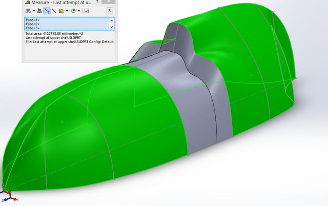
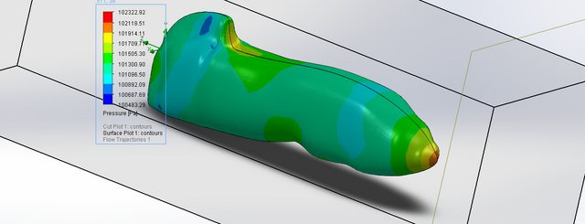
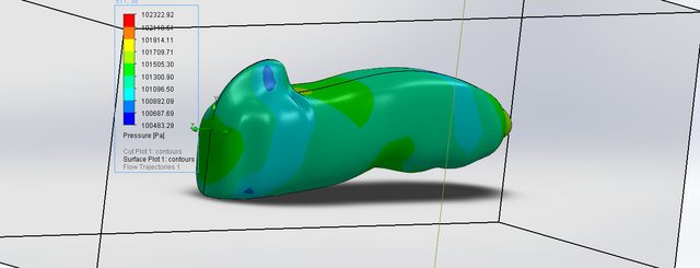
The fairing, and charging. Based on the highlighted green surface area of the first top I sketched out, I have 6400 square inches that I can put panels on. Round that down to 4000 for logistic/optimization/wasted space and I can fit eight 50W semi-flex monocrystalline panels. Now I don't expect 400W all the time but 200W alone would be absolutely crazy awesome, and a more realistic figure-- it won't all get direct light at once, anyway. I also might change the fairing design a bit to accomodate the panels, and I'll be running flow dynamics to minimize turbulent points. When I get some of the ergonomics of the frame under the beast in my model, I'll make a better fairing model with inlays for the panels; then I'll lay up carbon fiber over the whole printed mold as usual, but before I put any vacuum layers on I'll drop the panel on and route the cables through. I would think 400W of panels should be able to manage 300wh total even on mediocre day... and that's enough for my daily commute. And that one day when I get perfect sun and 400 watts out of them, and I'm pedaling up another 100+, and I'm averaging 30mi/h indefinitely... That's when my EV grin will hit my earlobes. =)
For wall charging, I think I'll build myself a 100 amp coil and get a few Eatons, and make a nice system behind a little flap in the fairing with a self-spooling 110V cable, NEMA 14-50, and J1772 routed right through the NEMA-14-50. And a big heatsink for my Max-E. With Samsung SDI-25R's I can rapid charge in an hour, should I need to, and the rest of the time they'll get a loving .25c charge and rest at a comfortable 50-70% charge. I should be able to go well over 300 miles if I economize and/or pedal, and should be able to ride 200+ miles with abandon (but probably not field weakening.)
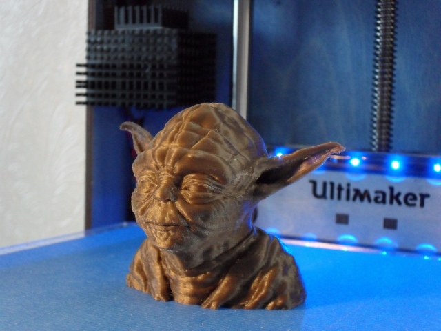
I know it's a lot to pack into a single vehicle but I don't see why it can't be done, as I've seen examples of all these bits by themselves. I'm about to get an Ultimaker 2 (i think, bartering) and it's capable of producing exceptionally precise (~20 micron resolution) FDM prints when tuned properly, so I could print a nice dash in Woodfill, my fairing mold, aero side mirror mounts, headlight mounts, NACA ducts, fenders or molds for composite fenders, etc... even nylon bushings or bearings, for small hinges and so forth. With such high resolution, it's easy to glue ABS parts together really solidly and get a nice finished piece with no visible joints-- after a little acetone vapor, anyway. Plus with infill you can make it lighter than sheeting...
I want it to serve as an all-weather vehicle with worry-free range, silent and comfortable operation with excellent suspension, lots of cargo space, good performance and handling, and integrated solar charging... for my ultimate goal; a vehicle that I can operate for 3,000 miles without plugging in to a wall, changing a tire, checking a dipstick, anything other than verifying things are working as they should. It's an arbitrary goal and bragging point. Of course I'll have longer term maintenance items with bearings, U-joints, suspension, and other linkages... but weather protection will go a long way in preserving those. I would like to have the frame done within a year, and the fairing done the next year. We'll see. I've been really really motivated but grad school is ridiculously time-consuming and I need to get a welding table before anything else, I think... large steel plates are expensive. I'll probably end up spending at least 5k all together and I might cannibalize my previous build too! But, I want it to be my transportation endpoint. Extremely custom, comfortable, reliable, and versatile.
I want it to be better than a car.
More models and simulations will come in the future... notably, the frame, and a more realistic fairing-- more teardrop-like. Which shouldn't actually take too long to put together as I already have sketches drawn up for many pieces. I'll also be printing basic jigs to accelerate the framebuilding process... using SHS for most of it. It will NOT be monocoque-- aint nobody got time for that!
I love my KMX/A123/Cro/Max-E build but I want something that's more comfortable, weatherproof, and has more storage. Then it'll be perfect...
My goals? Minimal maintenance, maximum comfort, maximum versatility, uncompromising performance. Too good to be true? I hope we find out! It'll have a Cro, Max-E, serial-hybrid drivetrain-- that is, regenning BB with a PAS, a seat that is either recumbent or pops up with the handlebars for motorcycle-like straddling that should even accommodate extra passengers, zero point-turn radius, awesome full-suspension all around, a geometric and possibly an additional pneumatic damping system to limit rapid tilting for safety in low-traction conditions. Oh yes, and I think I will get 800x Samsung SDI 25R cells, 2.5ah and "10c" rated, overblown number but they can manage 1c rapid charge and if the whole pack can discharge 80,000+ watts peak in ideal conditions, I think I can expect passable performance in the winter. With a 1-hour charge on a 200-300 mile pack, I should be able to ride across the country. Not to mention that I'll still be able to charge overnight off of 110v if I have to stop somewhere and they don't have J1772/NEMA 14-50.
I'll achieve these points with the following design elements:
Vertical leading link fork. This will facilitate several things-- firstly, its a good design for a suspended FWD hubmotor, very sturdy. Second, the geometry works well for zero-point turns, which will remain ergonomic via simple U-joint linkage. This linkage will also allow easy adjustment of handlebar height, which will facilitate yet another point; the back of my seat will be able to flip up near the headrest and lock up, so that I can ride upright if I want. At least part of the fairing will be attached to the handlebars, and raise with it. There will be doors, which will both move forward on the inside of the fairing
Short wheelbase. The front wheel will be vertically in line with my knees in a reclined position, this will increase load on the front and help with traction. This will also help in slippery conditions, and make those aforementioned zero-point turns quite negotiable. I plan on regen-braking a lot but I'm looking at getting a moto hydraulic brake and disc on my Cro... alternatively, some DH brakes should do.
Self-centering geometry. The rear swingarms will be designed such that leaning will increase the overall center of gravity as it moves from the midline, instead of lowering it like a traditional linear track vehicle. It probably won't be enough to reliably remain upright at a stop, I'll have a lean-lock for that, but it'll help dampen excessive leaning due to loss of rear traction (which should never occur anyway in a FWD setup-- if you can tell, I plan on riding in snow and ice) Furthermore, It'll be very easy to weld up spare, xtra-wide swingarms if I decide i need more track in the winter.
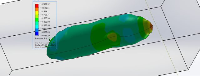
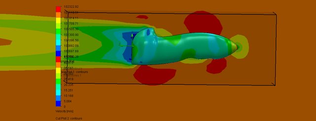
Full fairing with a bubble. I want to be able to hunker down and cut through the wind. I don't want to blink when I think about riding in -20F weather. Or 100F weather, I've already designed some NACA ducts that are basically drag-free, in fact, I'm thinking of printing a "Cromotor Wind Tunnel®" with a similar design, that will basically pump air through the motor. I'll need some good hardware, and I'll probably use a latch to hold it forward and some 50lb magnets to hold it against the seam strip when its pulled back over me.
Serial drivetrain. I plan on riding at speeds from 5mph among pedestrians up to 60mph on the highway, and if it's cold, I'd like to stay warm that whole time. I plan on using a reversed mid-drive and cheap 6fet for resistance and energy. It won't be as efficient as a chain drive, but I don't care about that with a 8.4kwhr pack-- I care about staying warm, and getting exercise, and this accomplishes that better than a complex chainline on a FWD leaner... Also, I really want it to be super quiet, and chains can be noisy. A single belt drive or maybe BAFANG should be pretty quiet though. And it should make PAS perform much better, as the resistance is constant regardless of your speed-- zero, or 60. So it'd operate almost like a torque throttle. It will also make for a less cluttered dash-- I'm going to have handy breakers for switching panels and pedals between the pack and the coils, and for many lights, speakers, and other accessories. And things add up fast. I'll probably have a switch to enable/disable PAS too.
Big ass trunk. I want lots of convenient storage, and a delta gives me room, so it'll be big. And you can bet that empty space under the flat bed of the trunk and behind the seat will be full of batteries. Since it'll lean, things won't even slide around. I'll have room in the front of the fairing too. I'm thinking about putting together a FOB for this thing, possibly Arduino based... if I do, then I would definitely
The fairing, and charging. Based on the highlighted green surface area of the first top I sketched out, I have 6400 square inches that I can put panels on. Round that down to 4000 for logistic/optimization/wasted space and I can fit eight 50W semi-flex monocrystalline panels. Now I don't expect 400W all the time but 200W alone would be absolutely crazy awesome, and a more realistic figure-- it won't all get direct light at once, anyway. I also might change the fairing design a bit to accomodate the panels, and I'll be running flow dynamics to minimize turbulent points. When I get some of the ergonomics of the frame under the beast in my model, I'll make a better fairing model with inlays for the panels; then I'll lay up carbon fiber over the whole printed mold as usual, but before I put any vacuum layers on I'll drop the panel on and route the cables through. I would think 400W of panels should be able to manage 300wh total even on mediocre day... and that's enough for my daily commute. And that one day when I get perfect sun and 400 watts out of them, and I'm pedaling up another 100+, and I'm averaging 30mi/h indefinitely... That's when my EV grin will hit my earlobes. =)
For wall charging, I think I'll build myself a 100 amp coil and get a few Eatons, and make a nice system behind a little flap in the fairing with a self-spooling 110V cable, NEMA 14-50, and J1772 routed right through the NEMA-14-50. And a big heatsink for my Max-E. With Samsung SDI-25R's I can rapid charge in an hour, should I need to, and the rest of the time they'll get a loving .25c charge and rest at a comfortable 50-70% charge. I should be able to go well over 300 miles if I economize and/or pedal, and should be able to ride 200+ miles with abandon (but probably not field weakening.)
I know it's a lot to pack into a single vehicle but I don't see why it can't be done, as I've seen examples of all these bits by themselves. I'm about to get an Ultimaker 2 (i think, bartering) and it's capable of producing exceptionally precise (~20 micron resolution) FDM prints when tuned properly, so I could print a nice dash in Woodfill, my fairing mold, aero side mirror mounts, headlight mounts, NACA ducts, fenders or molds for composite fenders, etc... even nylon bushings or bearings, for small hinges and so forth. With such high resolution, it's easy to glue ABS parts together really solidly and get a nice finished piece with no visible joints-- after a little acetone vapor, anyway. Plus with infill you can make it lighter than sheeting...
I want it to serve as an all-weather vehicle with worry-free range, silent and comfortable operation with excellent suspension, lots of cargo space, good performance and handling, and integrated solar charging... for my ultimate goal; a vehicle that I can operate for 3,000 miles without plugging in to a wall, changing a tire, checking a dipstick, anything other than verifying things are working as they should. It's an arbitrary goal and bragging point. Of course I'll have longer term maintenance items with bearings, U-joints, suspension, and other linkages... but weather protection will go a long way in preserving those. I would like to have the frame done within a year, and the fairing done the next year. We'll see. I've been really really motivated but grad school is ridiculously time-consuming and I need to get a welding table before anything else, I think... large steel plates are expensive. I'll probably end up spending at least 5k all together and I might cannibalize my previous build too! But, I want it to be my transportation endpoint. Extremely custom, comfortable, reliable, and versatile.
I want it to be better than a car.
More models and simulations will come in the future... notably, the frame, and a more realistic fairing-- more teardrop-like. Which shouldn't actually take too long to put together as I already have sketches drawn up for many pieces. I'll also be printing basic jigs to accelerate the framebuilding process... using SHS for most of it. It will NOT be monocoque-- aint nobody got time for that!
")