DogDipstick said:
I see 3x? And where/what is this BLE or Bluetoof jumper I am never supposed to use and what does it do and how might I get into trouble with it?
You might be right about 3 vs 4, I am cross-eyed. The specific jumper I am talking about is the 100mil (2.54mm) standard pin jumper I see in the picture. I did not read to see what it is for, but they are known for falling off. For jumpers we use solder pads these days.
As for BLE or the high power BlueToof
All of those (to a T) use UART and all modern microcontrollers use UART. This is just your RS-232 in 0-5V, your native terminal. When you attach to an Arduino you are hooking up to the UART via an FTDI USB converter. SO... The standard is to utilize an external bluetooth (really BLE) module - then that does not count against your power budget... and you can choose exactly what you want to use
S P E A K I N G
O F
W H I C H
I have had one of those "Bluetooth BMS's" cooking out in my garage for months. I am wondering what the leakage current is when it is not connected. I know when you connect with the phone it C H U G S current, so you have to be careful.
DogDipstick said:
Anyway, do you ever just measure the resistance of the fet banks to see if you can spot a clone, or a bad, fet bank? What clues do you look for, symptoms of a faulty BMS ( and I thank you for the other research you have done in the meanwhile... ).
You cant directly measure the ON resistance. You have to do it in the same way that you calibrate a CA
* Drive a constant current
* Read the resultant voltage Drain to Source
* Use Ohms Law to calculate the effective ON resistance
As for troubleshooting
I demonstrated in other thread. You always start in Diode Test on Fluke DMM. You look for the Body Diode. The mosfet can be in 3 states
* Shorted ON
* Blown OPEN
* Happy with Cathode on the Drain, Anode on the Source
We are talking N-Channel here of course
DogDipstick said:
Pick the first three off the top. Best words of wisdom I have heard all month, perhaps all year. Thankyou for that.
Yea... Mouser and Digikey have been competing for who can guess what you want to buy. Just like Amazon, they will push to the top what the other shoppers are buying. This is a way of anonymously breaching privacy and sharing what others purchased.
Mouser is even more obvious: They will be like: "Other People Bought This too"
This is the case where you need highly specific pins and sockets for some housing. Very helpful.
As for DIgikey
I have found that if the top 3 choices do not match your requirements then you are either
* Asking the wrong question
* Looking for a unicorn
DO NOT!!! Seek Tom Cruise Unicorns. Always go standard.
DogDipstick said:
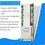
So I am installing one of these today, tomorrow, yesterday. Its interesting. Small for 200A and.. get this.. has a huge heatsink, that seems to be incorporated to the pcb! Very well soldered and good contact interface... However, I have a concern. I have to use about 1 1/2 foot plus... ( 14-18 inches) of BMS wire to distribute the cell voltage signals to the BMS headers from teh battery...... so that is going to be 21x ( 24g) wires carrying the cell level voltages from one area on the bike to another... anywhere from 14-18 inches long...harness... MY QUESTION IS....
Before I read your question, the answer is Kelvin Measurement.
The issue is that the balance taps can draw current over the very same lines that you are trying to take a sensitive measurement. This can easily get up into 10mV, 20mV, 40mV....
Now to read your question
DogDipstick said:
... should I worry bout such a long run? Will there be any consequence? Will such a long cell voltage harness be(come) an electrical problem down the line? Thanks in advance for the reply.
I can not advise you other than to say...
Yea, it will work
As you converge on balance your balance resistors will turn on less and less until they basically do not need to turn on. At that time you could read 20 feet of wire and get the same measurement. The only concern is ... slop... due to balance currents disrupting cell measurements.
* Larger Gauge Wire
When you extend something you UP GAUGE. This is the case where manufacturer says you can go 10 inches with 20AWG. Well... then I can no doubt go 20 inches with like... 16AWG, right? The problem is one of ohms law
V = I * R
Where I is the balance current
R is the resistance of the cabling per INCH
V is the error in your ADC readings
FINAL ANSER
Extend as far as you like, but upgage a notch or two. If they use 24AWG you may try 18 or 20AWG
DogDipstick said:
I once paid more to rub a dogs ass.
-methods