Solving the Variable Ebrake-Throttle Problem

OK, nailed it: Reduced R101 to 56 Ohms; this brings up the current through through the Opto-side to 53mA; if I read the spec right it says that the device can handle up to 80mA. UV starts at about 0.6V and terminates at 4.5V. That takes care of the Magura which is the most extreme case.

...
With a very slight adjustment on R103 and R105 I was able to dial in the HE Throttle too.

ADDENDUM: Added new output below fo the HE Throttle...
Spice-R12.Mod.V8B2.png

Red line is the Current (I) through the diode side of U1/4N25.

Alright, I'm breathing norml again :wink:

Can someone validate 4N25 forward current through the diode please? Presently it's about 53mA for both throttle configurations.
Many thanks, KF
 
Version 9 - For Prototype

Spice-R12.Mod.V9A.png


Greetings –

This is Version 9; it’s stripped clean of the rest of the Controller circuitry except what’s needed to model the mod. The component count increased as I refined the model, namely I decided to drop in smaller value POTs for greater precision and also a current-limiting resistor for U1. All the components have been renumbered.

R102 is really sensitive, and it could easily inhabit a 50 to 500 Ohm POT depending on what we need. R101 protects U1 from over-current – plain and simple. The other two POTs I swapped out from 20K to 5K because they are dialed in pretty tight now. R12 is now a 10K pull-down cos the OpAmps will drive UV output plenty over or under.

I don’t know what else to say; this is the version I plan to export to ExpressPCB for the layout of the breadboard. Something to do on a Sunday to keep me busy :)

~KF
 
I guess I'm a little lost here; this is moving faster than my eyes can keep up with :). The circuit was designed modeling SP, therefore assuming the signal came from that pin on the throttle connector.

Maximum "continuous" current on U1's LED is 60mA, and I would keep it below 30mA. It's usually not good to teak turn-on point with "that precision"; in practice each device is different and changes occur with temperature, so you'll never have a fixed setting. I think you should actually choose a different method to enable/disable the mod other than by "pass-controlling" the signal. U1's transistor has a voltage drop from collector to emitter, and this will add variable offset to your input signal (SP). Maybe use the transistor to turn on/off power to the ampop or put in series with R104 (if this works it would be ideal, since the ampop loop will overcome U1 device characteristics variations).
Ahh!! Or simply cut the ampop's negative rail using the EBREAK switch - then you wouldn't need U1 any longer although this may be a little tricky if currents flow through the ampop while it's off.

Remember: if you see the curves getting smooth to the end of the ramp's top, you may need to increase the ampop's supply voltage.

Is your controller R102 = 10K? I didn't get it why you changed it from 1K2 to 10K.

The scope is nice, I have that model too. What I don't like about it is the fan noise and the small screen. If you're not into "hardcore" electronics, maybe you should look at Owon, they have some nice big screen fan-less scopes, even a little cheaper.

As for ExpressPCB, I've used it and I liked it, very easy to use. However, not very advanced (at least at the time) and, above all, your designs get stuck to it, all file formats are proprietary.
 
Wow, that made a difference :D

Following your advice,
  • Removed R102.
  • Changed R101 to 300 which brings the current through U1 down to 10mA or so.
  • The top of R106 now plugs directly into the SP/SP-OUT line.
  • The top of R103 is now connected to the Emitter of U1 with the other side to +5V.
  • R107 and R108 had to be modified slightly cos we no longer have the slight resistance across C-E of U1 adding to the circuit.
  • Overall, regardless of SP starting voltage, U1 turns on with a 0.10 V lag (no problem with that) and we have nearly a perfect X-pattern as SP goes up and UV goes down. Very clean and one less POT. I rather prefer this method than have Ebrake connect/disconnect –Minus pin on the OpAmp. :)

R12 doesn’t have any affect unless it goes much below 1.2K. I have physically modified that resistor before and it’s a pain cos it’s a SMD. My plan was to remove it – thus expose the pads for the Mod to connect. In that case, we can make R12 have less influence and behave like a 10K pull-down; the OpAmp has plenty of drive up or down to override the need for parallel R12 resistors. Call it a personal preference. And actually… to prove the point I cut the leg of R12 away from UV and it doesn’t affect the circuit. That’s as it should be: This mod replaces R12 functionality.

Scopes:
OK, lets say we try to compare two scopes together...
  • Owon definitely has a bigger and higher resolution screen, though on the down side only a 10 Mpt deep memory... plus slightly more expensive.
  • Rigol has smaller less impressive screen, though a better price and a 100 Mpt deep memory.
  • Both are 2-channel and 1 GS/s sample rate. Both have USB.
Beyond the obvious, I cannot make a proper decision – though I will say I’m not bent over $30 and I’d lean toward the Owon cos of twice the resolution for $30. But the bigger question is will I notice the difference between 10 and 100 Mpts of deep memory? I haven’t a clue. For my first scope, what should I do?

ExpressPCB:
I just want to use it for board layout and nothing more just to imagine the packaging. :) If I were going into production I’d have to consider SMD because discretes take up a lot of room and there isn’t much inside the controller. Although a 1x1x3/8 PCB would likely fit inside a 6FET.

All this thinking has me feeling peckish (& thirsty), KF
 
Lebowski said:
Get the scope with the better screen. What do you need all that memory for ?

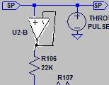
What is all the nonsence around U2-B ?
U2-B: That is a good point. The V9 schematic shows a typo; my bad :oops: The OUT of U2-A goes to the +IN of U2-B & R108. However I have tested disconnecting U2-B altogether I am not seeing a difference in the performance. If U2-B is not effective then perhaps we can remove R109 (and R12). If U2-B is disconnected, should I tied the inputs down?

Last night I conjured up a single-sided PCB - mainly to please myself. The old skills still exists 8) The board though came out about 1x1.2 inches. Alan B: I completely see it now; a MiniBoard could hold 6 circuits :lol:

Then reality set in as I measured the free space of one of my eariler modified 6-FET boards and there ain't a whole lot of room there boyz. :roll: Good thing I am presently using 12-FETs or it would be a struggle to shoehorn that board in. Maybe time to consider SMD instead of discretes?

Too much fun, KF
 
Kingfish said:
If U2-B is disconnected, should I tied the inputs down?
Tie the output to the negative input and the positive input to GND.

Kingfish said:
Last night I conjured up a single-sided PCB - mainly to please myself. The old skills still exists 8) The board though came out about 1x1.2 inches.
So... will you show it us :)?...
 
Njay said:
Kingfish said:
If U2-B is disconnected, should I tied the inputs down?
Tie the output to the negative input and the positive input to GND.

Kingfish said:
Last night I conjured up a single-sided PCB - mainly to please myself. The old skills still exists 8) The board though came out about 1x1.2 inches.
So... will you show it us :)?...
Cool thanks!

Will do as soon as I get the change in :)
~KF
 
Version 11

Like the amplifiers in Spinal Tap, my boards go to 11 man. Like, The Kingfish abides ya know 8)

- - -

Spice-R12.Mod.V11A.png


I call this the KISS version. Fewer parts, easier to calibrate, simple. My only negative about the design is perhaps that we have an unused OpAmp. I spent a little time trying to see if one could be had with one circuit instead of two… and I did find one that worked… but the price was way too expensive. Is there a single OpAmp solution that is inexpensive?

Spice-R12.Mod.V11B.png


With V10 (not released) and forward, SP and UV track together from start to finish; no fussing about with width. All we need to do is set the low & high limits of HVC. We done. :wink:

Spice-R12.Mod.V11C.png


PCB:
Been a while since I did a board. I am an old-timer and began PCB layouts using tape and X-acto blades; got pretty good at corners. Back then boards were done 4 or 10X up, then hung inside a walk-in camera and what you got back was an itty bitty negative.

This board here is about 1x1.2 inches x 3/8 inch tall. I took out R109 so it has a big hole in the layout. Looked into SMD and I think this board could be reduced by nearly 70% and only about ¼ inch tall. This particular design could be mapped 6X across an ExpressPCB MiniBoard for a cheap prototype run. I’ll probably just breadboard it and stuff it into the controllers. Small note: I provided two pads for SP cos we want the Throttle to come to this board and we also want to share that signal with the controller; in and out. Look Ma: No jumpers :mrgreen:

So – whatcha think? Are we there yet?
Getting thirsty, KF
 
I think you should keep R102. That will ensure there's no high potential at UV even when the mod has no power.

Don't know of any single ampop chip, at least not cheaper than LM358 :). The 2nd ampop could be used to buffer let's say SP, thus eliminating any influence the mod has on SP. Or interface between the opto and the resistor divider, to eliminate any influence the opto may have on the +5V.

Nice layout; you'll have time to optimize it after knowing if it works.

Ready for breadboarding, yeah!! Good luck :) (and don't kill yourself with a pack's high voltage! I assume you know what you're doing)
 
Njay said:
I think you should keep R102. That will ensure there's no high potential at UV even when the mod has no power.
Hmmm, R102 is (was) a POT. R101 keeps the current through the LED at about 10mA. Why not place a blocking diode just before UV to prevent reverse current? :)

Njay said:
Don't know of any single ampop chip, at least not cheaper than LM358 :). The 2nd ampop could be used to buffer let's say SP, thus eliminating any influence the mod has on SP. Or interface between the opto and the resistor divider, to eliminate any influence the opto may have on the +5V.
See C1 :) Dang cap takes up a bunch of room anyway... got to be good for something!

Njay said:
Ready for breadboarding, yeah!! Good luck :) (and don't kill yourself with a pack's high voltage! I assume you know what you're doing)
Never :p :lol: I know good and well how to fry a controller through carelessness. No need to repeat those sparkly events :roll: ...dang near caught my hair on fire too. That's why I always wear my ballcap <nods> cos ya never know when yer gonna blow it up. I'm pretty handy with a face shield too...

Nearly ready to commit, KF
 
Kingfish said:
Njay said:
I think you should keep R102. That will ensure there's no high potential at UV even when the mod has no power.
Hmmm, R102 is (was) a POT. R101 keeps the current through the LED at about 10mA. Why not place a blocking diode just before UV to prevent reverse current? :)
Sorry, I meant R12 (if not already inside the controller).

Kingfish said:
Njay said:
Don't know of any single ampop chip, at least not cheaper than LM358 :). The 2nd ampop could be used to buffer let's say SP, thus eliminating any influence the mod has on SP. Or interface between the opto and the resistor divider, to eliminate any influence the opto may have on the +5V.
See C1 :) Dang cap takes up a bunch of room anyway... got to be good for something!
Not the same thing :) (a typical 1uF is actually much smaller than that, by the way). Anyway, using it to buffer SP would be the best option, you don't need extra components, but you would need to power the thing with 12V because SP goes high above 3.5V.

Kingfish said:
Njay said:
Ready for breadboarding, yeah!! Good luck :) (and don't kill yourself with a pack's high voltage! I assume you know what you're doing)
Never :p :lol: I know good and well how to fry a controller through carelessness. No need to repeat those sparkly events (...)
Ok, go with your best face shield then :)

[damn thing just told me my message had too many smilies!! never eard about this 8 smilies per post limit]
 
We don't need R12; this circuit is the bypass for it. Let me evaluate without it. :)

Buffering: So how could I buffer SP with an OpAmp? I don't see it. :(

Although I understand swapping to +12V. On that note, why not just power it all with +12V?

BTW - this brings up a slightly OT question: I was looking at the 6FET controller schematic and spec for the LM317. I think the device outputs up to 1.5A. Using LTSpice, I modeled the circuit although I get an output of 24V – not 12V. Maybe I have something wrong.

Anyway – one of my crazy ideas that I want to do is to disconnect the LM317 and use my DC-DC converter to supply power to both my controllers, thus removing another heat source from inside the controller and a potential source of my sags/one controller cutting out when pulling the trailer up a hill. I’m trying to solve the problem from two directions: Upsize the battery harness and supply my own Class-A power to the controllers. I don’t have to worry about circulating currents cos everyone is on the same GND. I checked the DC-DC converter and although the GNDs are isolated, there is no potential between them, even under load. The converter outputs up to 60W and I use it to drive my LED lighting which consumes far less than 50%.

The potential cause of the sag is when the controllers are asking for power, drawing max current and momentarily pulling the battery main below what the LM317 can handle, so the +12V line drops or sags and the controller cuts out. The way I figure it, FETs (and UV) only see the battery voltage, and if I can generate my own 12V which has a direct line on the same bettery pack though much better buffered, why not send some juice back drive them ol’ FETs and keep’m happy 8)

Anyways… it’s just an idea to fix the controller-cutout problem. Gotta start someplace. :)
Suffering from dry mouth, KF
 
With 40/80 amps of battery current flowing and a few milliohms of resistance here and there, the grounds are NOT the same.

What you need to do to fix those problems is to re-reference the throttle to the slave controller, so the throttle signal is not waving all over the place.

Here is one example of a differential amplifier chip that can do that:

http://www.ti.com/lit/ds/symlink/ina117.pdf

It will precisely maintain the throttle voltage on the slave controller while the differential ground currents change the relative value of "ground" between the controllers.
 
Kingfish said:
My only negative about the design is perhaps that we have an unused OpAmp. I spent a little time trying to see if one could be had with one circuit instead of two… and I did find one that worked… but the price was way too expensive. Is there a single OpAmp solution that is inexpensive?

Not sure what your parameter limits are, but:

LM741, less than a buck each (some google "shopping" searches turned up medium qty orders 10-50 that ended up <40cents each):
http://www.mouser.com/ProductDetail/National-Semiconductor-TI/LM741CN-NOPB/?qs=sGAEpiMZZMtCHixnSjNA6JlKxGj6zye%252bxHqjHO7fKRQ%3d

UA741 30 cents each qty 1:
http://www.mouser.com/ProductDetail/STMicroelectronics/UA741CN/?qs=sGAEpiMZZMtCHixnSjNA6D8flKYNKtlVsaY2S4tJ1UE%3d

Dunno if this link will correclty bring up the filtered search, but:
http://www.mouser.com/Semiconductors/Amplifier-ICs/Operational-Amplifiers-Op-Amps/_/N-4h00gZscv7?P=1yzorcuZ1z0xwvdZ1z0yc08Z1z0yr2nZ1z0xuybZ1z0xv0nZ1yzogkbZ1yzordbZ1z0yz4qZ1z0y2bgZ1z0y1f8Z1z0y1yqZ1z0xw9wZ1z0z5l0Z1z0sn32Z1z0yrscZ1z0k084Z1z0xyf6Z1z0z7v3Z1yzrtjxZ1z0y33gZ1z0yz09Z1z0z31oZ1yzxavkZ1z0z7zfZ1yzoilmZ1z0z7csZ1z0z5o5Z1z0z7v5Z1z0jllrZ1z0yquvZ1z0yy2lZ1z0xr0oZ1z0y3nkZ1z0xn50Z1z0ys62Z1yzuv5yZ1z0xkccZ1z1414hZ1z1412jZ1z0z7ptZ1z0z63xZ1z0x0qfZ1z0wtpoZ1z0iym5Z1z0wtpcZ1z0wtpx&Ns=Pricing|0
Lots of 8pin DIP/etc single opamps there.
 
Kingfish said:
We don't need R12; this circuit is the bypass for it. Let me evaluate without it. :)
Keeping R12 (either inside or outside the controller) would be more like a safety feature, ensuring UV will never see a high voltage (the pack's voltage). Although there's a high series resistance (17.5K), that still allows a few mA flowing to GND, enough to fry the controller's microprocessor UV input pin. With R12 in place, the current flow from the pack through 17.5K and R12 will set a low voltage at UV "by default".

Kingfish said:
Buffering: So how could I buffer SP with an OpAmp? I don't see it. :(
See U2 as is now? This is called "unit gain" or "buffer" amplifier. Gain is 1 (so no change to input voltage) but the ampop can provide more current at the output while keeping it at the same potential as the input and not drawing current from the input. U2's positive input would come from SP and the output would go to R106.

Kingfish said:
Although I understand swapping to +12V. On that note, why not just power it all with +12V?
Go ahead! You'll have to re-adjust some parts, the voltage reference, the resistor for the opto's diode, ...

Kingfish said:
BTW - this brings up a slightly OT question: I was looking at the 6FET controller schematic and spec for the LM317. I think the device outputs up to 1.5A. Using LTSpice, I modeled the circuit although I get an output of 24V – not 12V. Maybe I have something wrong.
It needs a minimum load of 3.5mA. 1.5A is kind of a theoretical limit. In practice the power dissipated in the chip is usually too much to achieve that kind of output current.

Kingfish said:
The potential cause of the sag is when the controllers are asking for power, drawing max current and momentarily pulling the battery main below what the LM317 can handle, (...)
That would mean the battery voltage going below some 20V or so (assuming the control part of the controller draws some 200mA).
There's a trick which is to have a series diode on the positive rail to the 317 and then a beefy capacitor. Current will go in but not out, and the capacitor will hold the voltage while it sags (momentarily) at the pack. Actually there's already a capacitor there, you could add the diode (1N4007) on the input voltage VCC_L (I'm assuming the 6FET schematics).

amberwolf, the 741 needs symmetric power supply, meaning GND, a +V and a -V to work, and is still the same package size of the LM358. I actually buy LM358 around here for $0.27 single unit or $0.21 for 6 or more. Can't be more expensive than this in the US!
 
Lots to comment on…

Alan B:
I am unsure how to employ this device; certainly it appears to have a lot of value, though I don’t know where it would plug in as the examples of use are numerous. Perhaps with a bit of your help I could understand and learn? :? :)

Njay:
With R12 between U2-A OUT/UV and GND, I did note that as Throttle rises, Current through R12 drops about 1mA – from about 2.8mA to 1.8mA, and that UV changes range from 3.388-2.255 (w/o) to 3.338-2.256 (with); it was tiresome to reign it back in as R104 went from 2.5K to 2.31K & R107 from 2.6K to 2.89K. <phooey>. But the real problem is that R12 is not 1.2K, not on my boards cos I’ve already modified them for high-regen-braking -> it’s something like 835 or 935 ohms depending on which of my two controllers were talking about. (It’s at this point I begin ripping my hair out like Larry-Stooge and barking around in a circle on the floor like Curly). What I’m trying to say is that R12 is all relative. Why don’t we just replace it with a nice high-turn 2K POT and have a beer? :wink:

U2: Sorry for being dense, but I need you to explain it to me in terms of U2-A and U2-B because I can’t follow it. Or write over the image with the proposed correction, or reference a previous schematic where we may have had it drawn correctly :)

Switching devices from 5 to +12V: R104 will have to become a 10K POT as it falls right in between stock values for R106 (which was 14K & now 62K), and R101 went from 300 ohms to 1K. All good.

Vcc_L & Diode: Ha! I can do that now right after the keyswitch. My only sad thought was that both controllers would have the same 12-volt supply, but I will try this solution and see if it solves the problem. The C2 cap on my modified controllers is 100V 100uf. There’s not much room to stuff a bigger one, however for my DC-DC converter I placed a retired 63V 470uf cap on the +12V line which is why the voltage barely dips 0.05V when the Left-Right indicators are flashing. :) (It always cracked me up to watch the ampmeter on a car dashboard walk left-right when the flashers were going on/off while sitting at a stoplight, poor ol’ alternator struggling at idle to keep up with those lossy incandescent lamps… what’s with that?)

I’d show you Version 12, but it only has the changes discussed above which ain’t much. Gimme a proper U2 layout like you spoke of and I’ll do it pronto <nods>.


Cheerios or Fruit-Loops for breakfast?
No, make it Cap'n Crunch's Crunch Berries, KF :wink:
<gosh no wonder I went to the dentist so often…>
 
Kingfish said:
With R12 between U2-A OUT/UV and GND, I did note that as Throttle rises, Current through R12 drops about 1mA – from about 2.8mA to 1.8mA, and that UV changes range from 3.388-2.255 (w/o) to 3.338-2.256 (with); it was tiresome to reign it back in as R104 went from 2.5K to 2.31K & R107 from 2.6K to 2.89K. <phooey>. But the real problem is that R12 is not 1.2K, not on my boards cos I’ve already modified them for high-regen-braking -> it’s something like 835 or 935 ohms depending on which of my two controllers were talking about.
R12 has an influence on UV yes, but from a certain value up the ampop should rule. R12's maximum value should be one that puts UV at 5V under the highest pack voltage. You're free to go without it of course; all I can say is that If I did it for me, I would have an R12 (or a 4V7 - 5V1 zener diode, which would provide similar protection although a little more expensive but with the advantage of being independent of pack's voltage). The thing is that in certain situations, like at startup, things come up at different points in time in a "random" (although deterministic) order, and this is not easy to control.

Kingfish said:
Why don’t we just replace it with a nice high-turn 2K POT and have a beer? :wink:
You can take the beer, but should avoid pots as much as possible :), for several reasons, including but not limited to:
1) more expensive
2) bigger, which means more expensive again in terms of PCB size, weight, ...
3) mechanical moving parts, each means less reliable
4) an extra calibration parameter, each means more difficult to make it work
5) if the adjustment is needed, higher probability of design not being sound

Kingfish said:
U2: Sorry for being dense, but I need you to explain it to me in terms of U2-A and U2-B because I can’t follow it. Or write over the image with the proposed correction, or reference a previous schematic where we may have had it drawn correctly :)
An image is worth a thousand words :)

buffer.jpg
 
I like the Zener idea. Would this unit work: KDZ4.7B or 1N750 or the 1N5230?

U2-B: OK - I read you loud and clear :D

Here's the latest version...

Spice-R12.Mod.V12A.png


  • Was +5V, is now +12V
  • U2-B hooked up as SP-buffer
  • No R12, but instead a Zener (D2)
  • New values for R101, R104 & R107

Spice-R12.Mod.V12B.png

Voltage for SP & UV, and Current through anode of D2.

Spice-R12.Mod.V12C.png

PCB modified. Changes were a bugger to spoon in, but I got'r done Hoss :wink:

Where to next?
Lunchtime! KF
 
You need to check the zener's current at the highest possible pack voltage.

Then you can check how it behaves under temperature changes :). Add this to your schematics as a SPICE directive:

.temp 0 5 15 25 35 40

When you simulate, it will do one simulation for each of the mentioned temperatures (in deg Celcius) and draw the graphs on top of each other. Seeing a single graph (or roughly a single graph) is good news, means all the graphs are at the same places, meaning temperature doesn't affect the circuit in any relevant way.
Note: "Temperature" refers to the components' own temperature.

Ah, just noticed something. You're using 12V on U1's LED. This will make -EBS take 12V when the EBRAKE switch is open, and it probably isn't prepared for that, it's probably a microcontroller input, and therefore shouldn't take more than 5V.

You're still using resistor and pots with very weird values.
 
I'm still a little unclear on what you want the circuit to do.
From what I can gather:
Leave the throttle signal alone when the brakes are off, as well as the UV input.
When brake is applied, UVP gets fed a signal that varies from 2.25v to 3.38v depending on throttle signal and time.

Is this right?

Seems like the UV pad will have full pack voltage on it normally. If this pad is held down, won't it disable the controller? It would be possible to use a transistor to pull down the UV pin only when the brakes are applied.

You should measure the voltage on the EBS pin with the controller on. Is it really 12v? I'd guess 5v, but it could depend on the model of controller.
 
Njay said:
You need to check the zener's current at the highest possible pack voltage.

Then you can check how it behaves under temperature changes :). Add this to your schematics as a SPICE directive:

.temp 0 5 15 25 35 40

When you simulate, it will do one simulation for each of the mentioned temperatures (in deg Celcius) and draw the graphs on top of each other. Seeing a single graph (or roughly a single graph) is good news, means all the graphs are at the same places, meaning temperature doesn't affect the circuit in any relevant way.
Note: "Temperature" refers to the components' own temperature.

Ah, just noticed something. You're using 12V on U1's LED. This will make -EBS take 12V when the EBRAKE switch is open, and it probably isn't prepared for that, it's probably a microcontroller input, and therefore shouldn't take more than 5V.

You're still using resistor and pots with very weird values.
  • Zener & Temp: @ 63V, when EBrake is applied, Zener varies between 1.8 to 4.7 uA from 0 to 2V. When EBrake is open (n/c) Zener varies 2 to 14.5nA from 0.3 to 4.5V. Should I take that as being good? When Ebrake is open (n/c), current through Zener ranges from ~10nA @ 24V to about 18nA @ 100V.
  • When Ebrake was applied, there was no change in SP or UV when Battery was at 24, 63, or 100V.
  • Reset +12V to +5V; Good catch & my bad. -EBS is no longer a problem. I just want one source for power coming to the PCB. 5-Volts will have to do. R101 is back to 300 ohms, R103, 104 and 107 are similar to V11, but the Zener must have had some slight influence cos I had to twiddle a bit with them.
  • Resistor & POTs: Why are they weird? What should they be?? :|
Richard:
  • I have measured -EBS in the past and its' range is +5V or GND. When pulled to GND,Throttle is cut and EBrake is applied.
  • I will go measure UV on a live controller; I'll go do it here in a tiny bit and report back.

I'm still hungry. Maybe I'm part-Hobbit...
~KF
 
Kingfish said:
When Ebrake was applied, there was no change in SP or UV when Battery was at 24, 63, or 100V.
Sorry, I should have said that this is what matters that doesn't change with temperature nor voltage. The rest like the zener you just want it to be inside certain limits (mainly because of voltage, current or power). Up to a very few mA current through the zener is ok.

Resistor & POTs: Why are they weird? What should they be?? :|
Weird like 300, 62K and 3K. There are no such values in cheap common 5% tolerance resistors. You have either 270 or 330, 56K or 68K, 2.7K or 3.3K. As for the pots I get it, the values are just the adjusted point :)
 
EBrake: OK, so we're good then? :)

Resistors: I am picking values that are available and in stock from Digikey in either 1/10 or 1/8 W. Why not use what I can get? :)


MEASUREMENTS
Measurements were taken twice using two different multimeters.
The controller is my highly modified & retired/spare 6FET IRLB4030 Infineon XC846 from the 2010 Road Trip.

  • Vbatt = 56.0/56.3 (15S LiPo; slightly below 50% charge)
    +12V Rail = 12.09/12.1
    +5V Rail = 4.97/4.9
    -EBS = 4.65/4.3
    UV = 2.946/2.9
    R12 = 837/844 Ohms
R12 is in agreement with the copy of Hyena's R12 Spreadsheet: The calulated R12-average is predicted to be 835 Ohms, providing an HVC of 76.23 Volts ...which sounds right to me for this particular controller.

What else do you want me to measure? I can't hook it up to a motor and spin cos I'm just one guy in a hidden urban bat cave up the side of the hill clandestinely hiding from interesting natives in Redmond, Washington, and I think it would take one to hold the throttle, the other to hold the bike steady, and my third arm holding the controller whilst the other two take the measurements.

Suddenly, I feel thirsty again :twisted:
~KF
 
Back
Top