You are using an out of date browser. It may not display this or other websites correctly.
You should upgrade or use an alternative browser.
You should upgrade or use an alternative browser.
Space Vector PWM
- Thread starter Vihaan
- Start date
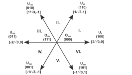
The document is nxp user guide page 48.
mxlemming
100 kW
- Joined
- Jul 17, 2020
- Messages
- 1,125
The switching states in the Star diagram are 3 phase, the U alpha and beta are 2 phase. The Star isn't actually a star but a Cartesian coordinate system viewed from the diagonal, so there are transforms...
The thing about this diagram and svpwm method is that it seems to have been copied between all the manufacturers appnotes with various degrees of omission and leaps of faith.
I'm 3 years into this, have written my own FOC code and have not once found these switching tables anything other than useless obfuscation.
FOC is
Measure current
Clark matrix transform
Park matrix
PID control on dq currents to get dq voltage
Inverse Park
Inverse Clark
Center and write those values to the pwm timer.
Don't make it more complicated than this. It doesn't need to be. I cannot find a single advantage of the mess that is space vector modulation.
Ok thank you very much for the reply, i am really confused with 2 other questions, i don't get answers
1. When we apply FOC what is the maximum bus voltage applied on the phases (line voltage or phase voltage), if the applied voltage from the power supply is Vbus. I read it is 2/sqrt(3)*Vbus. Is there a simple derivation?
2. Similarly if the input DC current is Idc what is the phase current applied. I mean what is the relation if the torque applied is T?
Thank you in advance.
mxlemming
100 kW
- Joined
- Jul 17, 2020
- Messages
- 1,125
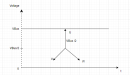
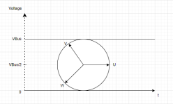
1) is very simple. Just draw two lines labeled 0 and Vbus. Now rotate the 3 phase star inside those two lines... What's the maximum length of the Star arms (phase voltages) that can rotate in that space? Simple triangle trigonometry. This should be self evident... The inverter cannot output voltages outside 0 to Vbus.Ok thank you very much for the reply, i am really confused with 2 other questions, i don't get answers
1. When we apply FOC what is the maximum bus voltage applied on the phases (line voltage or phase voltage), if the applied voltage from the power supply is Vbus. I read it is 2/sqrt(3)*Vbus. Is there a simple derivation?
2. Similarly if the input DC current is Idc what is the phase current applied. I mean what is the relation if the torque applied is T?
Thank you in advance.
2) is trickier but still simple. The equation is
VbusIbus=3/2(Vqxiq+Vdxid)
This comes from 3 for 3 phases
1/2 is from the fact that it's sinusoidal so we have to convert to rms current and voltage since FOC uses peak currents and voltage by convention (it's just easier this way).
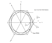
This is what i tried but got stuck up. Could you please help me with next steps?1) is very simple. Just draw two lines labeled 0 and Vbus. Now rotate the 3 phase star inside those two lines... What's the maximum length of the Star arms (phase voltages) that can rotate in that space? Simple triangle trigonometry. This should be self evident... The inverter cannot output voltages outside 0 to Vbus.
mxlemming
100 kW
- Joined
- Jul 17, 2020
- Messages
- 1,125
You don't need the circle. You have to imagine rotating it without the circle. The middle would go up and down if the vectors were bigger but that's not a problem.This is what i tried but got stuck up. Could you please help me with next steps?
View attachment 341288
I'm not doing the basic trig for you...
stancecoke
100 kW
- Joined
- Aug 2, 2017
- Messages
- 1,824
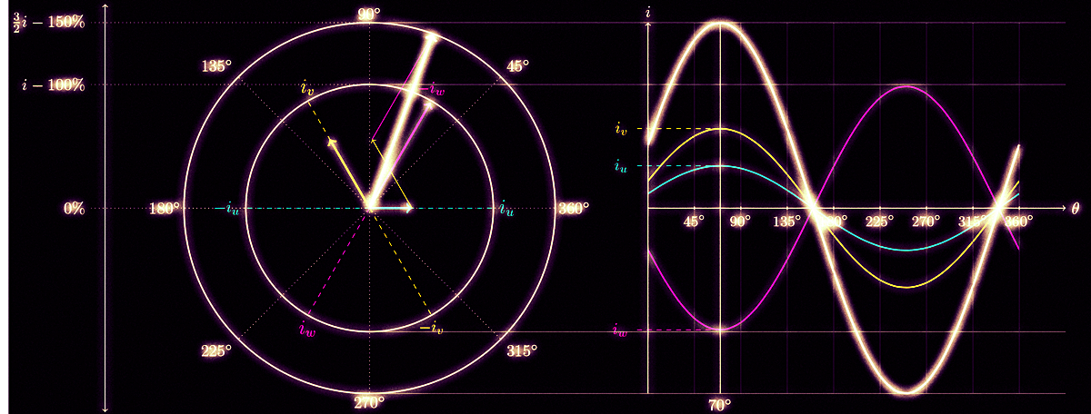
I like this explanation very much:
 www.switchcraft.org

 www.switchcraft.org


Vector control for dummies — Switchcraft
Who doesn't want to get a quick and dirty understanding of the concepts behind vector control?

Space Vector PWM Intro — Switchcraft
Get rich, smart and famous by understanding the dark arts of space vector pulse width modulation! A must for everyone aspiring to become a star in the drives community!

Last edited:
mxlemming
100 kW
- Joined
- Jul 17, 2020
- Messages
- 1,125
A
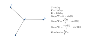
Think harder.View attachment 341296
I think it is VBus/2 the maximum vector of U.
Similar threads
- Replies
- 9
- Views
- 558
- Replies
- 15
- Views
- 903
- Question
- Replies
- 8
- Views
- 595


