Super fun but is there more????

Mikeeal

10 µW
Joined
Oct 8, 2023
Messages
6
Location
Northern NV
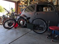
Good evening to all, we recently put a 1500w front hub (eBay) on a stretch bike fed by a 48v 20ah battery. I mounted a "saddle bag" ammo can to store the battery. It's great fun and does 30mph. HOWEVER, I am now fighting the urge to add another hub to the rear, second battery and ammo can. The ONLY reason I want to do this is for more top speed. After thinking about this for a few weeks it dawned on me this may not add any more top speed just more torque/acceleration? Is this correct? I mean the max RPM on these hubs are what they are so adding a second isn't going to change that right?

Am I way off? Here's the bike currently, my son just built a Coleman 200 with a stage 1 224cc and walked away from me earlier so I gotta admit I'm a little salty:

PXL_20230927_233207490.jpg
 
Roughly, more watts = more torque, more volts = more speed, up to the point where air resistance takes more watts to go that speed than you have available.

You can get a good idea of how the system parts work together to do what you want over at the ebikes.ca motor simulator.


If the motor you have spins way faster offground than while riding, then you're power limited already, and you might get more speed by changing to a higher current controller and a battery capable of supplying that current without sagging in voltage.

How much more current depends on the watts you need to go the speed you're after (the simulator can help you find out how much that is, but it rapidly grows the faster you want to go (more or less exponentially rather than linearly).


I don't know gas engines very well, so: based on a quick google search, it takes about 750w (1hp) for every 22cc of displacement (this will depend on the actual engine used, and the specifics of the electric motor competing against it, etc).
Mar 15, 2019 — 1 hp = 746 watts. 1000 watts/746 watts/hp = 1.34 hp. A typical fuel injected gas engine develops 1 hp per 22 cc.

So if you have 1500w now, that's about 2hp, or 44cc. If he's got 224cc, you might need a 224 / 22 = 10.2 x 750w = 7600w to match him. Depends on his gearing, actual engine performance, and your motor winding vs battery voltage and any gearing (wheel size the hubmotor is in or that plus gearing between the wheel and a mid-drive motor).

Torque / speed curves are different too, so you might end up with a system that pulls out way faster than his, but then can't match his speed--so you'd have to do the math to figure out what is required to beat his specific actual performance.

You could need much more power than that, or less, but it's tough to fit that on a bicycle frame if you want more than drag-race power (a battery to supply that kind of power will be either large or expensive and/or have very little range at those power levels; too small a battery means really high C-rate cells or abusing lower-rate cells and heating them up a lot and wearing them out quicker).

You'll probably need high voltage for high speed; doubling the voltage on a given motor doubles it's no-load (offground) speed, but may need more than double to double the actual road speed. If you're at 48v now, 96v+ might be your next step (and seriesing lower voltage batteries doesn't usually work out at these voltages if they have individual BMSes)

QSmotors makes big hubmotors like the QS205 that could do short peaks of that power, or bigger ones like the QS275 that could do it continuously. Dual smaller hubmotors can spread the load but be heavier in total, or middrive motors can spin faster and be smaller but geared down to drive the wheel at the same desired speed.

The controller for 8kw+, at 96v+, only has to pull about 84A from the battery to provide that kind of power; this current increases at lower voltages (the battery has to supply this, with as little voltage sag as possible--every volt of sag is that many more amps that has to be pulled from it to give the same watts, which makes it sag more and heat up more inside, etc).


Then you have the limitations of your bike: can it actually be ridden at the speeds you want, without problems like death wobble or other uncontrollable steering issues, or folding up trying to brake, etc?
 
Nice bike ..
If you want more speed , you need more volts since motor rpm is directly related to voltage ( Kv)%
You may also need a controller that will accept the higher voltage without melting.
a new controller coule also push more amps to the motor giving more power.
 
Yo @amberwolf I really appreciate the time you took to reply! Thank you. You've sure given me lots to look into I'm looking forward to the research.

Thank you @Hillhater also for the info and compliment. My immediate question to you would be can the hub motor I have now advertised at 48v handle anymore voltage? The listing said use a battery with 48v OR 52v so I sent a message asking for clarification on that and they recommended I use a 48v pack so that's what I went with.

Such a different world with these bikes, I'm in real deep with brushless/lipo RC's with one 1/5 scale running on 12s (50v) all the way down to 1/10 scale 2s (8v) stuff but these bikes don't relate at ALL it seems. I certainly get the AH of the packs from this experience but that's about it unfortunately.

Thanks y'all.
 
Same principles; you're just dealing with a lot less mass and lower air resistance, etc. in the smaller RC stuff.

When you get to bigger stuff like the one on your wall, you start approaching the power requirements of smaller scooters with small riders, for example.

(many of the really small scooters or eskates actually use RC motors and controllers including wireless handheld remotes).


Brushless motors can generally handle at least a couple of hundred volts. The "rated" voltage of one is the voltage at which it will provide the "rated" speed in the diameter wheel it comes in.

So a hubmotor in a 26" wheel that is rated as 20mph at 36v will give proportionally higher speed at 48v, 52v, etc.

The controller, on the other hand, has a limit defined first by whatever parts it has inside it (usually less than 100v, often far less than that), and then by it's firmware and sometimes hardware, as some of them have HVC (high voltage cutoffs) that disable the controller above a certain voltage, to prevent damage to it during some kinds of operation where a motor generates voltage while in motion that could be higher than what the controller could take.
 
Such a different world with these bikes, I'm in real deep with brushless/lipo RC's with one 1/5 scale running on 12s (50v) all the way down to 1/10 scale 2s (8v) stuff but these bikes don't relate at ALL it seems. I certainly get the AH of the packs from this experience but that's about it unfortunately.

Thanks y'all.
Without knowing the brand/model of the motor, its impossible to say for sure…
….however, most of these type of generic hub motors can be overvolted considerably, its the controller that will likely be the bottleneck as they generally use cheap components rated for no more than 60v, with little tolerance for abuse.
As you likely know, the higher voltage battery and controller are the most expensive parts of the electric drive.
 
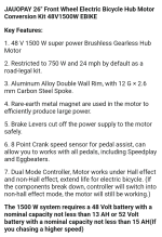
I'll have to inspect the wheel itself this week as the specs listed don't seem to say much:

Screenshot_20231009-065223.png

I have no problem getting a better controller and bigger battery, say 72v???? The motor will maybe handle that? Sounds like I'll just have to keep an eye on temps?
 
As above FME a dual motor setup with a rear 1000w, 52V DD system and a dedicated 36V 350 front PAS (I realize this is pretty small) really improved acceleration but top speed was only affected minimally. Probably you'll be able to match you son (depending on gearing etc) off the line, but I doubt in top speed. I'm probably poor at this since 35 mph is about the max for me on the street.

Added: AFAIK, the "48V" system's controllers are limited to 60V, so 14s (52V which fully charge to 58.8V) is the largest you can utilize with the stock controller.
 
As you attain more speed, don't forget to factor in safety, the faster you go the longer it takes to stop it, and high-speed wobbles are no fun either. Have fun, but do it safely :)
 
If you're at 48v now, 96v+ might be your next step (and seriesing lower voltage batteries doesn't usually work out at these voltages if they have individual BMSes)

Can anything be done about this? Would be great if I could buy another 48v pack vs buying a new 72v or 96v.
 
I'll have to inspect the wheel itself this week as the specs listed don't seem to say much:
Inspecting it wont' tell you much, if anything. Most of the motors don't have a marking on them for their kV or RPM/volt, or even something like a voltage. (some do, in their serial number...but not most). You'll have to actually test it offground vs onground for max speed at your present voltage.

Also, those specs say it's limited to 24mph (which is wierd, as there is nowhere I know of with that speed limit; it's 12, 15, 20, or 28, for all the ebike laws I am aware of around the world). So if that's the speed you get out of it, exactly, then you'd have to bypass the speed limit by whatever method the instructions provide (or that you can find around the forum or internet that works for this specific controller), or change to an unlimited controller. Nevermind...you already get 30 out of it. :oops:


I have no problem getting a better controller and bigger battery, say 72v???? The motor will maybe handle that? Sounds like I'll just have to keep an eye on temps?

The motor will handle the 72v...but as already noted, if you're trying to beat his bike, you'll have to determine what his bike is capable of, figure out how much power that takes under the specific riding conditions you have to do it in, and then buy parts that will supply and handle that much power.

If you just want it to be "faster than it is now", increasing the voltage will do that. By how much depends on the actual speed you need to reach, under your specific riding conditions, and how much power you already have, vs what those will need to reach them.

A 96v pack with sufficiently high current capability and a matching controller could double the no-load speed, but is unlikely to double the on-road speed without melting the motor you have. A big heavy QS205 could probably do that dragracing (very short runs with time to cool off), but it would probably take a bigger heavier QS280 to do it continously. (or a middrive like a QS180, etc).

You are probably going to need to beef up the dropouts / torque arms for the higher torque you'll get. I recommend just removing the existing dropouts entirely (those look like steel forks) and welding on some pinching/clamping dropouts; see The Torque Arm Picture Thread for various examples, including even the very crude ones I made on my SB Cruiser heavy-cargo trike.

If you use the regen braking at all, then in addition to the above I *highly* recommend you get a controller with variable / proportional regen braking, like pretty much any FOC controller should be able to do, so that you can apply the braking like you would with mechanical brakes, rather than the sudden shock-load the on/off braking most controllers do, which is applying all that sudden intense braking force to the extremely tiny section of your axle flats that contacts the torque arm flats--note that because almost all of those arms are poorly made with poor fit, that is *not* the entire surface that overlaps--it is only the *edge* of the surface. (that's why the clamping ones are better, because you can force full contact of all available surface area...it's still not the best way, but without heavily modifying a motor with a new different-style axle, it's the best you can get).

Can anything be done about this? Would be great if I could buy another 48v pack vs buying a new 72v or 96v.
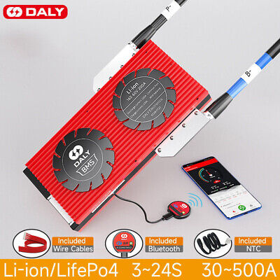
If you are experienced with wiring batteries in series (and understand the risks), and can deal with the high voltage hazards, you can open up both batteries, remove their BMSes, buy a 96v BMS, and wire them all up as one big 96v pack. If your 48v packs are 13s, then your resulting pack will be 26s, so that's what the BMS has to be for. (52v is 14s). If you do this I recommend a JBD "smart bms", preferably one that is contactor-based instead of FET-based, as there are more options to a contactor-based system and it's less prone to failure from design flaws in the FET drivers and shutoff conditions).

If you have to, you can operate without a BMS, and use your RC chargers to balance cells as needed (wiring up new balance leads that fit your charger's capability for series cells, that you can access from outside the pack). If you do this, make sure to set your controller's current limit and LVC, etc., conservatively so that the pack is not used outside it's limitations, since you have no base layer of safety protection against cell damage this way.

Note that whatever pack you get to series it should be as identical to the first as possible, so that all the cells perform as closely as possible. They wont' be matched so there will always be imbalances even if it's a quality pack (which it probably isn't--most out there are pretty crappy, some are decent, few are quality and virtually none are well-matched cells).
 
Can anything be done about this? Would be great if I could buy another 48v pack vs buying a new 72v or 96v.
That will work. Just hook them up in series and get a controller that can handle 96V. Be careful what frame you are putting these on. Go too fast on a goofy frame and you will get the 'death shakes' at speed.
 
That will work. Just hook them up in series and get a controller that can handle 96V.

Work...yes, but they probably won't be safe.

It's not all that likely that the FETs in a 48v pack will handle 96v.

If they don't, then as soon as one of the packs shuts off it's output because of any BMS limit being exceeded (like if it has an empty cell group), the full voltage of both packs will be across the FETs that have turned off. When this happens, they'll be damaged or outright fail.

FETs usually fail stuck on. If that happens, then the pack that should be turned off and be safe from overdischarge is now being forced to continue to operate, supplying current even though a cell is empty, so it's now overdischarging that cell. Continuing to do this will eventually reverse that cell's voltage, which is much worse to do to one that just overdischarging it, as far as internal damage goes that can lead to fires.

Because the BMS can't talk***, it can't tell you that any of this has happened--it's entire capability to prevent damage that can lead to fires consists of turning those FETs off, which it did. So the end-user will never know this problem and damage has occured or that the BMS can't protect the cells anymore, and will continue to depend on the BMS to do a job it can't do, so even if the first damage doesn't result in catastrophe, the likelihood of it eventually happening rises with every further usage that runs the pack down to empty and overdiscahrges or even reverses the cell(s) again.


So...I don't recommend seriesing packs with their own BMSes, unless you are *certain* the design of the BMS and the parts it uses cannot cause this type of failure...once it does happen, you can't know it has happened, unless you are manually testing the functionality of the BMS every time you use it (which is almost certainly never going to be done).


There is a potential way to "bypass" this problem, by using diodes in reverse-parallel with each pack's discharge connection (see various posts by Fechter in the various "seriesing batteries" threads over the years)...but the diodes have to be able to handle the full discharge current of the system--even if only for a moment as the system shuts down from insufficient voltage--or they may fail and if that lets the voltage across the FETs, then you still have the same problem.


It's just safer not to do the seriesing.


(you'd also still need to use each pack's own 48v charger, and those must be electrically isolated from each other, or else when you plug them both in you'll short across one of the packs and chargers and either blow a fuse or damage charger/BMS or even cause a fire--you don't want to use a 96v charger on seriesed packs like this, or you have the same fault possible on the charge ports).


***If you have a smart BMS with bluetooth and actually monitor it all the time with the phone app, you'll see the overdischarged voltages (as long as the reversal of voltage doesn't cause the sense input to fail), and could do something about it, but you still can't know the FETs are stuck on--the app will say they are off becuase it can't tell what state they're in, only what the BMS told them to be).
 
You might look at the NBPower 3,000w, 72V kit on Amazon since the rear is 135 mm (which your bike should be able to accommodate). I think there was a thread that suggested the motor was manufactured by MXUS. We don't know the capability of your son's bike, but, even modified, a Coleman 200 might be slow enough for you to keep up. Of course,as above, beef up the dropouts, don't employ regen and buy a new battery. Maybe sell the front kit to partially fund the new bike.
 
Work...yes, but they probably won't be safe.

It's not all that likely that the FETs in a 48v pack will handle 96v.

If they don't, then as soon as one of the packs shuts off it's output because of any BMS limit being exceeded (like if it has an empty cell group), the full voltage of both packs will be across the FETs that have turned off. When this happens, they'll be damaged or outright fail.

FETs usually fail stuck on. If that happens, then the pack that should be turned off and be safe from overdischarge is now being forced to continue to operate, supplying current even though a cell is empty, so it's now overdischarging that cell. Continuing to do this will eventually reverse that cell's voltage, which is much worse to do to one that just overdischarging it, as far as internal damage goes that can lead to fires.

Because the BMS can't talk***, it can't tell you that any of this has happened--it's entire capability to prevent damage that can lead to fires consists of turning those FETs off, which it did. So the end-user will never know this problem and damage has occured or that the BMS can't protect the cells anymore, and will continue to depend on the BMS to do a job it can't do, so even if the first damage doesn't result in catastrophe, the likelihood of it eventually happening rises with every further usage that runs the pack down to empty and overdiscahrges or even reverses the cell(s) again.


So...I don't recommend seriesing packs with their own BMSes, unless you are *certain* the design of the BMS and the parts it uses cannot cause this type of failure...once it does happen, you can't know it has happened, unless you are manually testing the functionality of the BMS every time you use it (which is almost certainly never going to be done).


There is a potential way to "bypass" this problem, by using diodes in reverse-parallel with each pack's discharge connection (see various posts by Fechter in the various "seriesing batteries" threads over the years)...but the diodes have to be able to handle the full discharge current of the system--even if only for a moment as the system shuts down from insufficient voltage--or they may fail and if that lets the voltage across the FETs, then you still have the same problem.


It's just safer not to do the seriesing.


(you'd also still need to use each pack's own 48v charger, and those must be electrically isolated from each other, or else when you plug them both in you'll short across one of the packs and chargers and either blow a fuse or damage charger/BMS or even cause a fire--you don't want to use a 96v charger on seriesed packs like this, or you have the same fault possible on the charge ports).


***If you have a smart BMS with bluetooth and actually monitor it all the time with the phone app, you'll see the overdischarged voltages (as long as the reversal of voltage doesn't cause the sense input to fail), and could do something about it, but you still can't know the FETs are stuck on--the app will say they are off becuase it can't tell what state they're in, only what the BMS told them to be).
Of course AW is correct. I forget that people run a BMS these days. Myself, I don't trust them. (Battery Murdering System) I use RC chargers and monitor individual cells myself. I have a CA and pay attention to it so as not to drain the battery. I charge to 90% and discharge to 80%. There are lots of ways to go about this. This is just the way I do it.
 
Generally anyone buying a premade battery is going to end up with a BMS in it. It might be crappy, and it might not have balancing, and it might not even be able to handle the current the pack claims to, but it'll be in there (even if the cells aren't what they say they are, etc). ;)

It's certainly possible to bypass it or even remove it...but if it's in there most poeple won't modify the battery (and shouldn't!), and will simply rely on the BMS to keep the battery safe from them.

So...that's why I don't recommend seriesing batteries that have a BMS.

Anyone that knows enough about the systems and the way they work to be comfortable modifying the batteries internally has a good chance of also knowing how to work around the problems and/or monitor things themselves so a failure doesn't end up as a fire. (no guarantees, but...)
 
First off thank you all for the replies.

Secondly, I agree with @amberwolf 's last paragraph of the last reply fully, I've said similar to new lipo users, something to the effect of "if you know what you're doing you wouldn't be asking these questions" lol and here I am doing the same 🤣🤣🤣

WITH THAT SAID, let's see if I'm on the right page so far cause I think I still definitely want to move forward on this. I'm pondering two options that both require the same knowledge to accomplish,

Option 1 (72v): remove my current 48v pack and shelf it for a future build, get two 36v packs, new controller, remove BMS's and wire up one 72v BMS with packs wired in series.

Option 2 (96v): actually same as option 1 but instead get a second 48v pack (same as I have now), controller, again remove 48v BMS's, wire up 96v BMS in series.

My justification for two separate packs vs one is because of where I'm mounting the batteries. (Saddle bag ammo cans) so I have room for two 36v or 48v packs no problem but not enough for a single 72v or 96v pack. From what I've seen I don't even think the common 60v packs will fit in the ammo can.

Some things I've looked at the last week,

New controller I saw recommended on another thread:

FLIPSKY 75100 FOC 75V 100A Single ESC with Aluminum PCB Based on VESC for Electric Skateboard/Scooter/Ebike Speed Controller https://a.co/d/0hMc09g

72v 150a BMS:


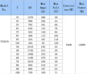
Side note, it's crazy to me the amps being pulled in these systems, I would have thought they'd be much higher vs my larger RC's considering the weight but I guess not. For example check out these specs from a motor I'm using on 8s (1400kv) it's 300+ amps!

Screenshot_20231014-111519.png

Last thing to note for now, I'm very confident with my soldering abilities regarding this project, I still just don't know exactly what I'd be soldering/desoldering 🙄

I appreciate the safety concern comments too, I'm shopping much nicer front forks with functioning suspension to start.

EDIT: Found this article too:


I think I'm going to be patient, be content with my 30mph for now while studying up until I know enough of what I'm doing to build my own packs. By then I would hope I've not only grasp the other supplies I'll need like the BMS but feel confident I'm building a quality pack.
 
Last edited:
I think I'm going to be patient, be content with my 30mph for now while studying up until I know enough of what I'm doing to build my own packs. By then I would hope I've not only grasp the other supplies I'll need like the BMS but feel confident I'm building a quality pack.
🏁🏁🏁
 
With another Frisby-sized motor and addidtional batt. added to it, that bike would weigh a ton.
I would think 30 mph without any suspension would be enough.
 
Back
Top