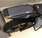
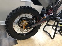
Suzuki RMZ 250 EV Restomod

Eastwood, found the bending post and found the welder on amazon, Danke!

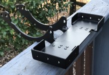
Battery tray:
You could also add strips of 2mm or 3mm rubber, which will keep the battery raised above any moisture on the bottom and absorb some shock too.

Yes exactly my friend 👍
I have a rubber strip that will be glued/silicone to the battery tray. Pretty much any point of contact where the battery touches the frame there’s rubber between. There’s also rubber inside the battery case between the battery and the case. I went a bit overboard with rubber lol, but I feel like it will help absorb vibration from off-road use.

It’s quite the task being my very first battery build for the most extreme conditions for a lithium ion battery pack lol. If you think about it, a trail bike is probably the most vulnerable place for a lithium ion battery because of the water, vibration and wrecks.

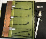
Been working hard on this battery tray and almost ready for paint. There’s been so many tedious steps with making this tray, but it’s just part of the process. 🤠

Here’s a link to the welder if anyone’s interested. Use 7018 “AC” version rods with this welder. The arcing with these cheap inverter welders work better with AC rods, although it’s DC.
Link to the auto darking welding mask
 
Last edited:
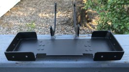
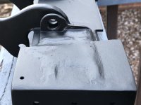
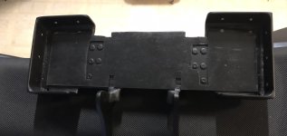
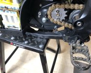
Finally finished the battery tray/motor mounts. It’s a bit heavier than I was wanting but very strong. I considered drilling some large holes in the bottom plate, but I didn’t wanna compromise the strength.


Everything was welded at 90a 7018ac electrodes. At first, I was trying to use 6013 rods, but there was so much splatter. The 7018 rods lay a nice bead.
IMG_0011.jpeg


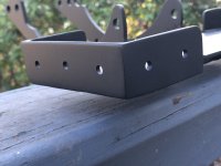
I think the paint finish turned out beautiful. Those holes drilled are for the carbon fiber battery shields. Have some waterproof rivets to hold everything in place.
IMG_0012.jpeg
IMG_0016.jpeg


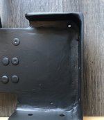
Here you see one of the drain holes, One on each side. The welds had to be filed down flush so the battery can sit flat. Took me hours to grind down all of those welds on both sides. I put epoxy to fill in all of the cracks and crevices to keep the water out.
IMG_0008.jpeg


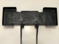
Then here’s a pic of the bottom. Welded the bottom side as well. used the same epoxy to fill in all the cracks and crevices to keep mud from getting trapped. Will make cleaning a lot easier.
IMG_0014.jpeg


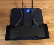
The weight turned out to be 3.5lbs.
IMG_0022.jpeg


Edit:
Lastly, I need to silicone this rubber gasket into place. This is so the battery can sit flush and not sit on top of the rivets.
IMG_0024.jpeg
 
Last edited:
Small update. Got the rubber gasket glued in place. So basically, the rubber gasket is glued to the battery tray, and then the bottom of the battery case will be glued to that gasket. This should eliminate the possibility of Water getting between the battery case, and Tray.
IMG_0045.jpeg

Decided to put on a couple decals on last night. The decals/graphics are pretty plain, there’s no brands or writing or any crazy designs.
IMG_0040.jpeg
IMG_0046.jpeg

Almost ready to put the battery tray and motor mounts back in the bike and I can finally get started back on finishing the battery.
 
Small update. Got the rubber gasket glued in place. So basically, the rubber gasket is glued to the battery tray, and then the bottom of the battery case will be glued to that gasket. This should eliminate the possibility of Water getting between the battery case, and Tray.
View attachment 349281

Decided to put on a couple decals on last night. The decals/graphics are pretty plain, there’s no brands or writing or any crazy designs.
View attachment 349282
View attachment 349283

Almost ready to put the battery tray and motor mounts back in the bike and I can finally get started back on finishing the battery.
I always get ahead of myself and start doing paint and stickers way before I'm finished. Then I end up needing to cut or drill or remake the part that I "finished". You're a more patient man than me
 
Great Build -
Im building a eYZ
I ordered similar busbar kit for a surron battery -
I see you put small spacers on top of each cell - why ?
Do you have any tips on using / spot welding cells in busbar -
Thanks
 
I always get ahead of myself and start doing paint and stickers way before I'm finished. Then I end up needing to cut or drill or remake the part that I "finished". You're a more patient man than me

Well I do feel like this build has pushed me to the limit of my patience 😅
I’m ready to ride some trails, it’s been months since I’ve ridden which is too long for me. All is good though, I’ll keep chipping away until I get this bike finished.

Great Build -
Im building a eYZ
I ordered similar busbar kit for a surron battery -
I see you put small spacers on top of each cell - why ?
Do you have any tips on using / spot welding cells in busbar -
Thanks

Thanks
What Spacers are are you referring to, the yellow strips?

As far as any tip for spot welding, I would just say practice on some old cells until you get welds just right. This is my first battery build, so I’m still learning. I have many builds under my belt, including gas bikes, but this is the first lithium ion battery I’ve ever built.
 
Got the battery tray/motor mounts with the motor Installed.
IMG_0108.jpeg

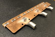
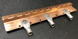
Working on the top of the battery/4th level. Need to get this sorted because this will determine overall height because the positive discharge wires coming off the top of the battery. I’ve bent the positive discharge busbar the same way as the bottom of the battery. I’m debating if I will put the lugs under the discharge busbar or on top like these two pictures below. If I install below the busbar it gives me more clearance for the top of the battery case.

On top 👇
IMG_0105.jpeg

Then the lugs below the busbar👇
IMG_0103.jpeg

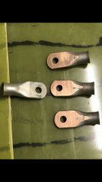
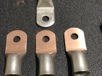
Then for the battery lug connectors, I like to resurface to allow for maximum contact between the busbar and lugs. You can see there’s a quite a bit more surface area now compared to the lug on the left that hasn’t been resurfaced. I used some 320 grit sandpaper on a flat piece of steel too resurface. I will resurface the bus bar as well, where the lugs connect, without removing too much material.
IMG_0104.png

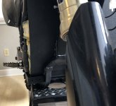
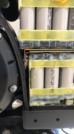
Here’s a side view of how wide the battery will be. 11p is the perfect width because 12P would’ve made the battery stick out too much. The carbon fiber shields will make it appear to be a little bit wider, but I felt like that was needed to create a gap between the impact shields, and the battery case so there’s no chance of impact on the actual battery case. The shields will connect on the inside of that battery tray, have some high strength waterproof rivets. The of the carbon fiber shields will be bolted to the frame on the front and the side. Thankfully I could use some factory mounting holes.
IMG_0101.jpeg
 
Last edited:
Ok, smoothing out the lugs is something I had for whatever reason never thought of. and the number of times I have had at lugs with vices hammers and anger is fairly high. My love of over-gauge wire has lead to some very funny scenes of my big bum doing gymnastics inside of vehicles never meant for such antics.

::reaching for a file:: thinking of which. I have an appointment with a set of batteries in my suburban...
 
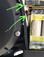
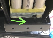
So there’s a slight gap between the battery and the case
IMG_0116.jpeg


I would rather there be contact between the battery and case so the rubber can help absorb vibration.
I slid this into place, Looks like a perfect fit. When I add layers of rubber together, I use black adhesive sealant silicone RTV.
IMG_0118.jpeg


The bottom of the battery sits on this rubber block that is 15.5mm thick.
IMG_0119.jpeg


For the part of the battery that sits on top of the motor, there’s another rubber block about 20mm thick. Still sorting out the exact thickness on this block.
IMG_0121.jpeg

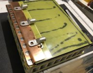
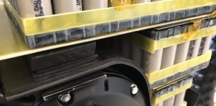
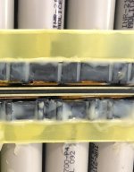
I used this sandwich method I came up with for insulation between each level 👇.. the rubber was used in the middle of the sandwich method to help absorb vibration.
1mm FR4 board, then
1.6mm rubber layer,
Then another 1mm FR4 board.
Also, all of the copper busbars are covered with kapton tape.
IMG_0118.jpeg
 
For the contact point I have had pretty good luck allowing motion.

Gonna do my best to explain this...

Make a form that follows the outside of the unit being supported, lay in your RTV and cover it with plastic film or whatever you wish to use which will conform to the final shape of the item being supported.

While the RTV is still malleable and not fully set, but after it has skinned and is no longer prone to running stick it in place so it cures with a shape that conforms to the item to be supported. You end up with a piece that can move rather than jar on impact and doe not limit the motion of the batteries.

If that fails to make sense outside of my head lemme know. i can draw up a diagram to try and explain it better.
 
For the contact point I have had pretty good luck allowing motion.

Well, with this battery all the contact points have rubber between with various density depending on the location. Technically there is some movement but it’s very minimum, just enough movement to help with absorbing vibration.

Make a form that follows the outside of the unit being supported, lay in your RTV and cover it with plastic film or whatever you wish to use which will conform to the final shape of the item being supported.

While the RTV is still malleable and not fully set, but after it has skinned and is no longer prone to running stick it in place so it cures with a shape that conforms to the item to be supported. You end up with a piece that can move rather than jar on impact and doe not limit the motion of the batteries.

Thanks for the input.
Yes, I’ve use this method before it works great! Sometimes I will just put a light layer of oil or wax over the item I’m covering and then I can put the silicone or epoxy straight on the item. Once it cures, it pulls right off with a perfect mold.
 
someone told me you could scmeer glue stick on and it eventually arrives at that effect because the glue stick eventually cures out to a fine powder... I will try oil next time.. I have some denatured fish oil that ya pack metal for duration storage......
 
Will have to put the lugs underneath the positive discharge busbar because I'm not able to slide the top of the battery in the bike without hitting the frame if the lugs are on top. It’s a super tight fit but doable 🤠

So I resurface the top of these lugs and now they have much better surface contact.
IMG_0128.jpeg

IMG_0145.jpegIMG_0146.jpeg
Once I crimp the wires to the lugs I will then use DP-420 epoxy around the edges of the lugs to make it permanent. Same as did on the bottom side of the battery.

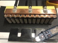
Here’s a picture of the bottom side of the battery, which is the negative discharge busbar. As you can see, the epoxy is around the edges of the lugs, and also on top of the nut holding everything together permanently. I was very cautious to not allow epoxy to seep under the lugs to get between the surface contact. Anyways, I will be doing the same method to the top of the battery.
IMG_0147.jpeg

Haven’t made much progress in the last several days been too busy working. At least got this busbar bent into shape the holes drilled for the lugs. If anyone’s wondering those extra holes in the busbar, that’s from the factory, I told them not to drill holes but no big deal.
 
I need to source materials to set up bus bars like that, they look veddy slick and I like it better than the always sloppy looking when I I do it copper/nickel strips I use now.
My past week has been a bloody nightmare of inefficiency.. I did manage to score a truckload of air compressors, but that is another story...
 
Did you put some epoxy on top of the lugs, after you bolted them to the busbars? How badly will this inhibit servicing in the future?

Just looking at pros and cons. You need a lot more current draw than I ever will, so I usually just stick with reinforced mechanical connections: flange nuts, lock washers, lots of surface area, ect. Personally I prioritize serviceability over permanence. But probably you've already taken that into consideration. Besides, you're going off roading, and you'll experience a lot more vibration and potential loosening than I ever will so I can totally see why you're going with epoxy.
 
Besides, you're going off roading, and you'll experience a lot more vibration and potential loosening than I ever will so I can totally see why you're going with epoxy.

Yes exactly, because of the off-road use. I would’ve settled for some high temperature thread locker if I were building a bike for the street. Also, I was concerned that if one of those nuts came loose and started bouncing around inside the battery it could cause a short.

Did you put some epoxy on top of the lugs, after you bolted them to the busbars? How badly will this inhibit servicing in the future?

Yes, I put epoxy on top of the lugs and nut after a bolted them.
As far as it inhibiting servicing, it won’t. Once that busbar is spot welded to the cells you can’t get to the bottom side of the bolt or nut anyway to remove so that’s another reason why I made it permanent. Plus, there would be no reason to service the discharge wires, they will be well protected from the elements or impacts. Will double layer heat shrink with marine grade heat shrink so the glue seals it off nicely.

The goal is to not have to service this battery. That’s kind of why I’ve been taking so long and methodically thinking through every possibility and scenario. I mean, obviously a cell can go bad which would need to be fixed but everything was evenly matched so hopefully I will have a pack that stays well balanced for a long time. That’s the goal at least 😅

I need to source materials to set up bus bars like that,

Or just buy them from Wellgo. They laser weld that nickel strip to the copper busbar. I seen doctorBass doing some testing on these busbars recently, and they had very low resistance. I think it’s due to the fact the way they laser weld the nickel strips to the Copper busbar.
 
Last edited:
Here’s a picture of the bottom side of the battery, which is the negative discharge busbar. As you can see, the epoxy is around the edges of the lugs, and also on top of the nut holding everything together permanently. I was very cautious to not allow epoxy to seep under the lugs to get between the surface contact. Anyways, I will be doing the same method to the top of the battery.
View attachment 349960

Haven’t made much progress in the last several days been too busy working. At least got this busbar bent into shape the holes drilled for the lugs. If anyone’s wondering those extra holes in the busbar, that’s from the factory, I told them not to drill holes but no big deal.
Nice and clean, well done :bigthumb:
 
Looking very tidy! Are you going with 3 x 1/0 cabling for the battery cabling? I'm going a similar power 28s build with max 450A discharge (~10s) and am settling the design on a single 1/0 cable. Cheers
 
Looking very tidy! Are you going with 3 x 1/0 cabling for the battery cabling? I'm going a similar power 28s build with max 450A discharge (~10s) and am settling the design on a single 1/0 cable. Cheers

Thanks!
Well sort of, it’s 3 x 1/0awg off the battery but then that connects to 0000awg going to the Contactor, controller etc.. It’s over kill but Just trying to maximize efficiency

With Connecting one single cable to the discharge busbar, could possibly create a hotspot. If you can spread out the current flow across the busbar it should help keep the temperatures down.
Thanks, that makes sense, especially with the 11P connection and wanting to balance the resistance across all cells as best possible 👌
 
Back
Top