I designed and built these packs a year ago. After a couple thousand miles of testing and considerable internal debate, as a service to the DIY community and as a social experiment, I'm releasing the design publicly.
You use my design and any information contained in this discussion thread ENTIRELY AT YOUR OWN RISK! Lithium ion cells pose serious shock, fire and explosion hazards!
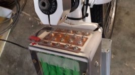
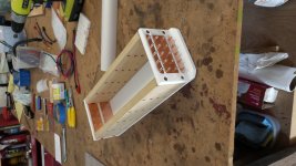
It should be obvious to anyone skilled in the art or who has given some thought to battery pack building how this design works. And I'll say right out of the gate this is best suited to being produced on a large 3D printer. I don't have that tech and thus built these 100% functional prototypes as a very close tolerance woodworking project.
Soldering cells together is messy, inconsistent, and potentially heat damaging; spot welding cells requires some specialized equipment and lots of nickel strip and shapes that are not optimally conductive and it's permanent and slow going... and with both of those DIY approaches you still have to heat shrink the whole thing and put it in some floppy bag or something and create some half-assed attachment to your ride.
I didn't want to deal with any of that. Nor did I want to use hundreds of nuts and bolts or springs or magnets or pressure foam or other inefficient types of conventional cell arrangements.
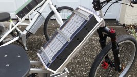
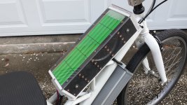
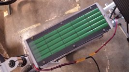
With my optimized end-to-end design you quickly load your cells into a rugged electrically non-conductive case, adjust them, and go.
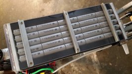
I don't believe a BMS is necessary. I'M the BMS. There is instant DMM access to each parallel cell group down one side to check voltage and at the ends for pack V.
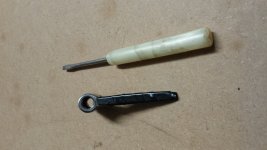
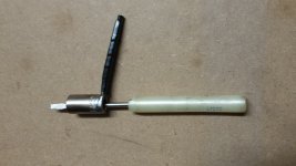
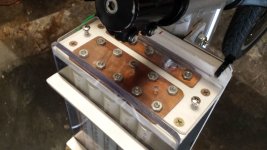
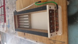
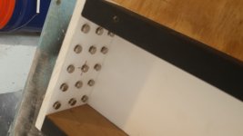
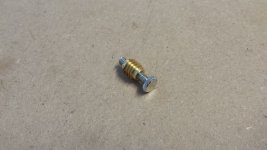
The compression adjustment is done with reversed Dremel slotted nickel plated lamp screws riding in carefully plumbed threaded brass inserts, and locked with simple hex nuts with a socket that has a short handle welded to it through which a small screwdriver is inserted. The adjacent external busses MUST be taped off during adjustment to avoid serious shock.
The cells are only free to move longitudinally. The clearance tolerance on the inside case width and height is +.001"- .005". Obviously there is room on one case end for adjustment which allows loading/unloading cells. There are .032" polycarbonate insulating sheets between each layer of cells.
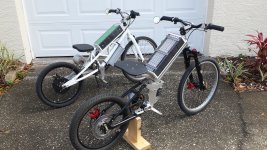
My main concern during early testing was possible shoulder shorts. That concern proved unfounded. Scrupulous prep of used cells is required however and all overwrap on the cell negative ends was removed with a sharp razor knife to maximize electrical contact. 100% burr free hand sanded .025" copper strip was used to make the parallel connections in the case of the green 20s5p battery. The 15s5p gray 21700 pack uses 3/4" flat braided copper instead for much higher amp rating.
So there it is guys. Works great, looks cool. It's a design feature not a detriment. Only limitation is it's gotta be rectangular...
So I'll see how the reaction goes here. If you make one for personal use and want to kick me a small donation- great.
The real social experiment is who's going to start producing it for sale without giving me a dime. That's where the honor system comes in. I'd work with a commercial developer and provide additional details.
You use my design and any information contained in this discussion thread ENTIRELY AT YOUR OWN RISK! Lithium ion cells pose serious shock, fire and explosion hazards!
It should be obvious to anyone skilled in the art or who has given some thought to battery pack building how this design works. And I'll say right out of the gate this is best suited to being produced on a large 3D printer. I don't have that tech and thus built these 100% functional prototypes as a very close tolerance woodworking project.
Soldering cells together is messy, inconsistent, and potentially heat damaging; spot welding cells requires some specialized equipment and lots of nickel strip and shapes that are not optimally conductive and it's permanent and slow going... and with both of those DIY approaches you still have to heat shrink the whole thing and put it in some floppy bag or something and create some half-assed attachment to your ride.
I didn't want to deal with any of that. Nor did I want to use hundreds of nuts and bolts or springs or magnets or pressure foam or other inefficient types of conventional cell arrangements.
With my optimized end-to-end design you quickly load your cells into a rugged electrically non-conductive case, adjust them, and go.
I don't believe a BMS is necessary. I'M the BMS. There is instant DMM access to each parallel cell group down one side to check voltage and at the ends for pack V.
The compression adjustment is done with reversed Dremel slotted nickel plated lamp screws riding in carefully plumbed threaded brass inserts, and locked with simple hex nuts with a socket that has a short handle welded to it through which a small screwdriver is inserted. The adjacent external busses MUST be taped off during adjustment to avoid serious shock.
The cells are only free to move longitudinally. The clearance tolerance on the inside case width and height is +.001"- .005". Obviously there is room on one case end for adjustment which allows loading/unloading cells. There are .032" polycarbonate insulating sheets between each layer of cells.
My main concern during early testing was possible shoulder shorts. That concern proved unfounded. Scrupulous prep of used cells is required however and all overwrap on the cell negative ends was removed with a sharp razor knife to maximize electrical contact. 100% burr free hand sanded .025" copper strip was used to make the parallel connections in the case of the green 20s5p battery. The 15s5p gray 21700 pack uses 3/4" flat braided copper instead for much higher amp rating.
So there it is guys. Works great, looks cool. It's a design feature not a detriment. Only limitation is it's gotta be rectangular...
So I'll see how the reaction goes here. If you make one for personal use and want to kick me a small donation- great.
The real social experiment is who's going to start producing it for sale without giving me a dime. That's where the honor system comes in. I'd work with a commercial developer and provide additional details.
Attachments
-
 20220213_110531.jpg5.4 MB · Views: 1,504
 -
 20220213_110600.jpg4 MB · Views: 1,492
 -
 20220213_110627.jpg3.4 MB · Views: 1,488
 -
 20220213_112441.jpg3.6 MB · Views: 1,488
 -
 20220213_112619.jpg3.1 MB · Views: 1,485
 -
 20220213_112519.jpg3.4 MB · Views: 1,489
 -
 20220213_113112.jpg3.1 MB · Views: 1,496
 -
 20220203_124143.jpg2.3 MB · Views: 1,492
 -
 20220203_124156.jpg2.1 MB · Views: 1,489
 -
 20220213_111440.jpg3.1 MB · Views: 1,492
 -
 20210124_145944.jpg2.8 MB · Views: 1,496


") . Sturdy, optimal surface area/electrical contact, and it utilizes the inherent but subtle "springiness" of the positive cell cathodes. Fortunately they can be safely compressed in series without passing (or probably even nearing) their yield point. This works both with the thin copper paralleling strips or the even more vibration damping flat braid copper. Trying to use springs instead would introduce unnecessary complexity and poor electrical contact.
. Sturdy, optimal surface area/electrical contact, and it utilizes the inherent but subtle "springiness" of the positive cell cathodes. Fortunately they can be safely compressed in series without passing (or probably even nearing) their yield point. This works both with the thin copper paralleling strips or the even more vibration damping flat braid copper. Trying to use springs instead would introduce unnecessary complexity and poor electrical contact.