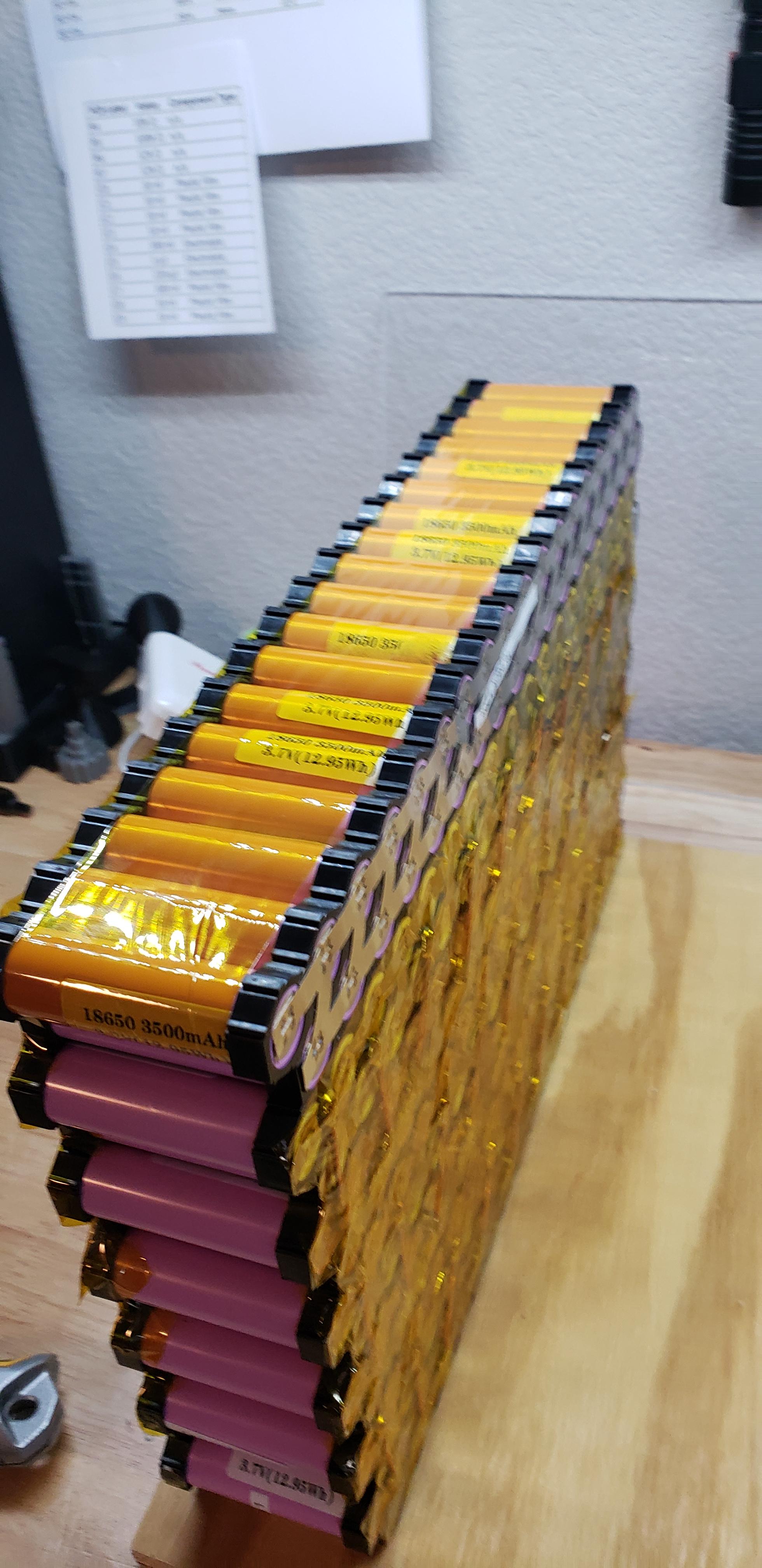
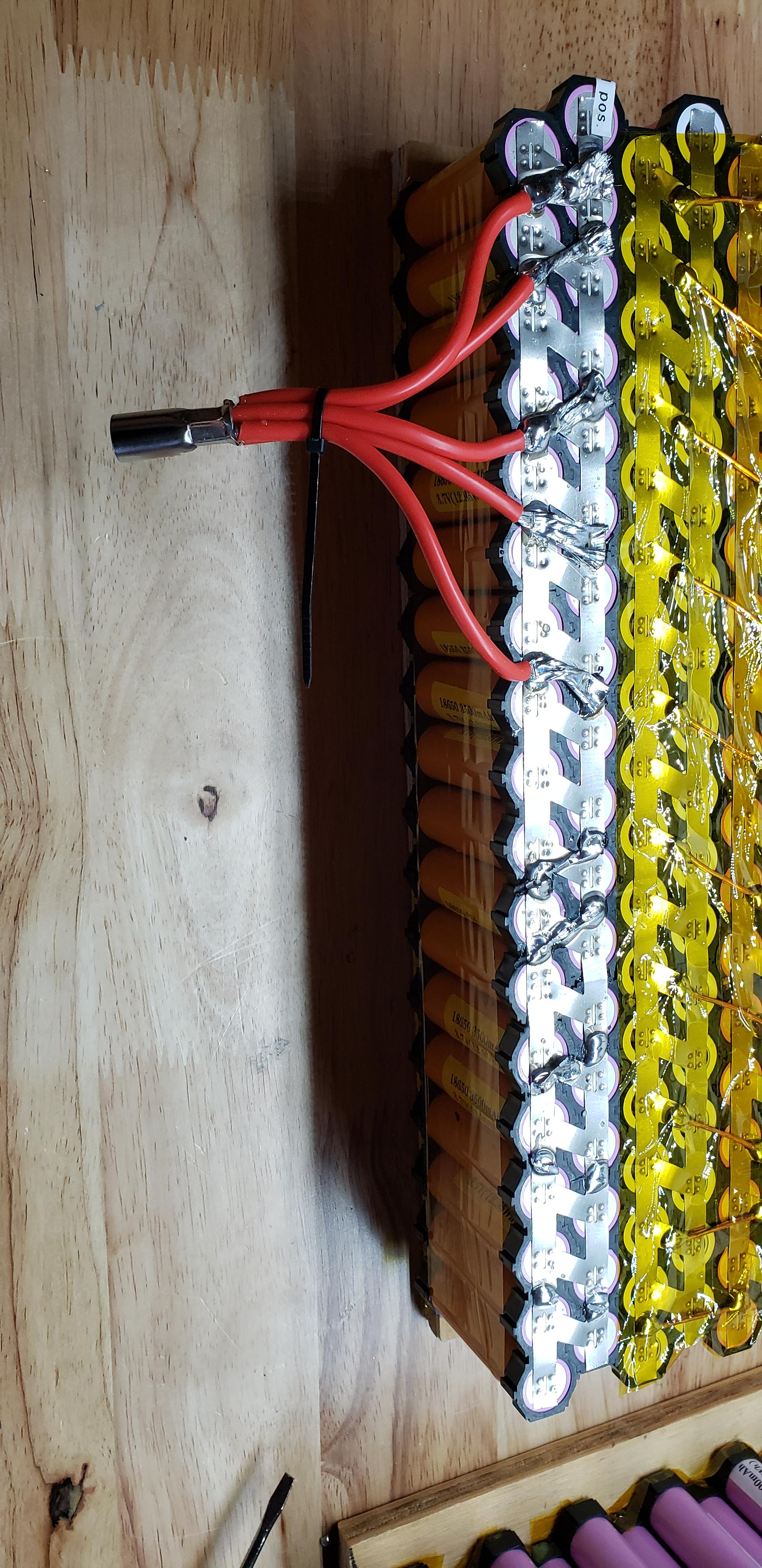
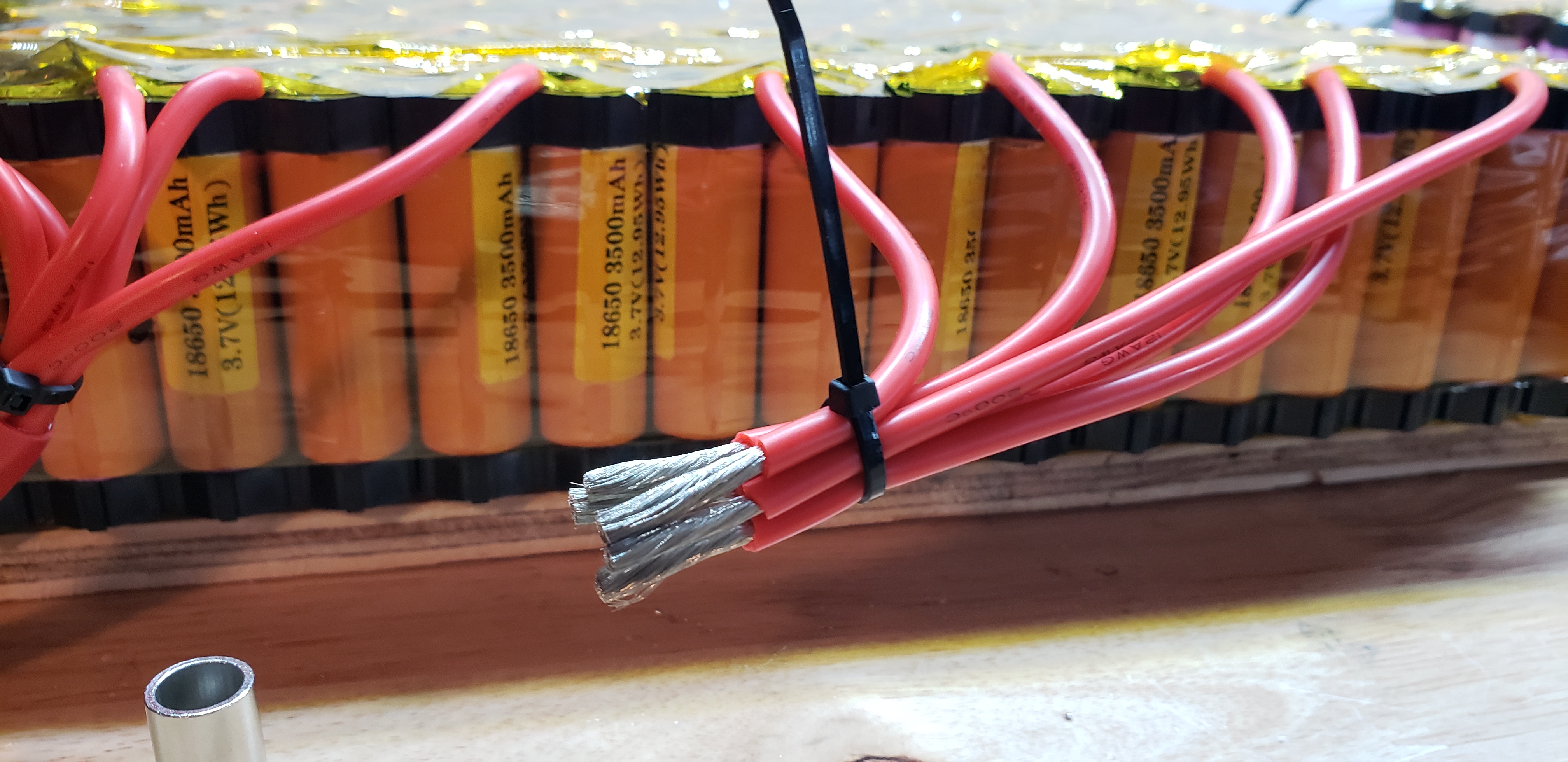
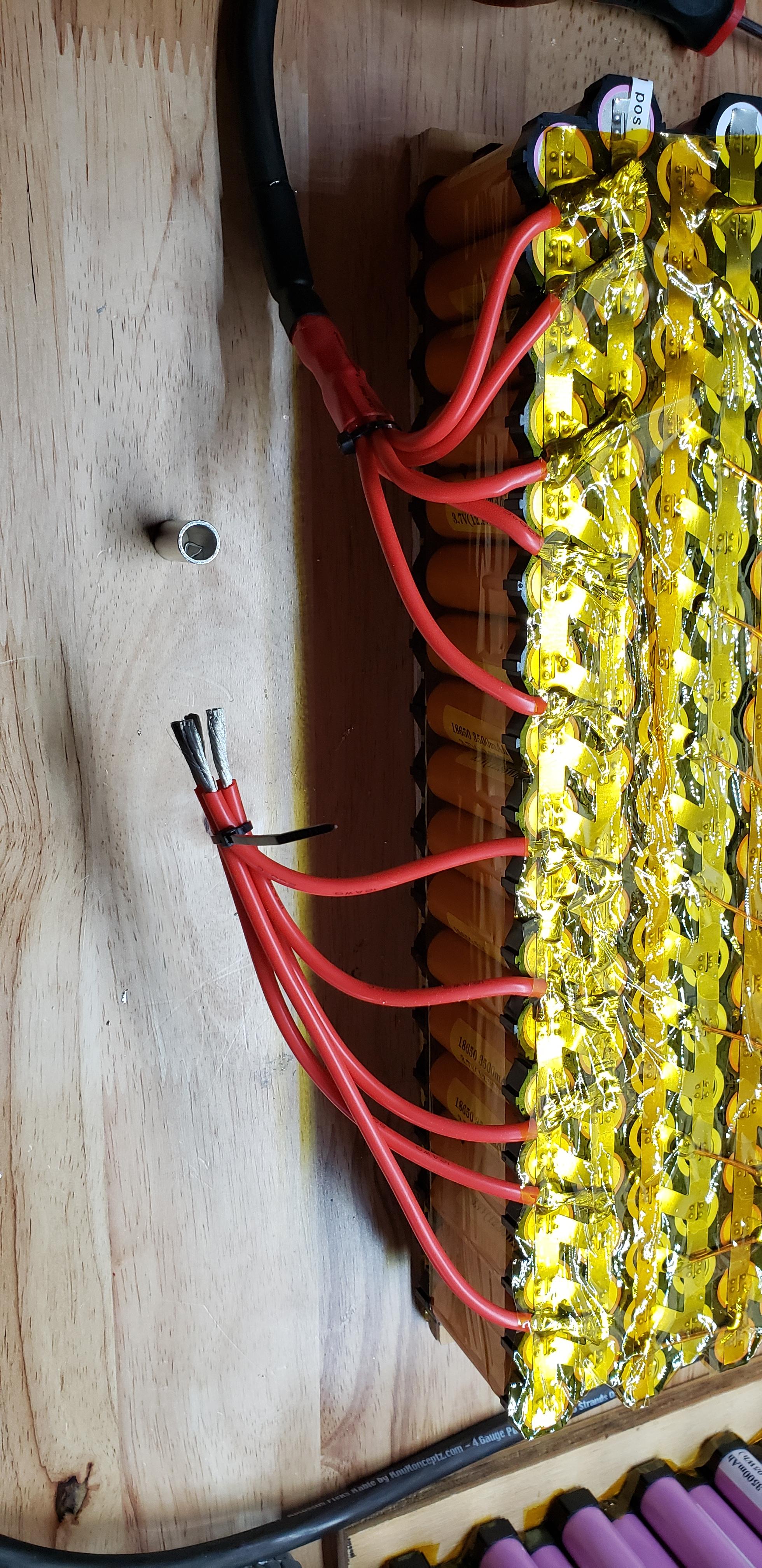
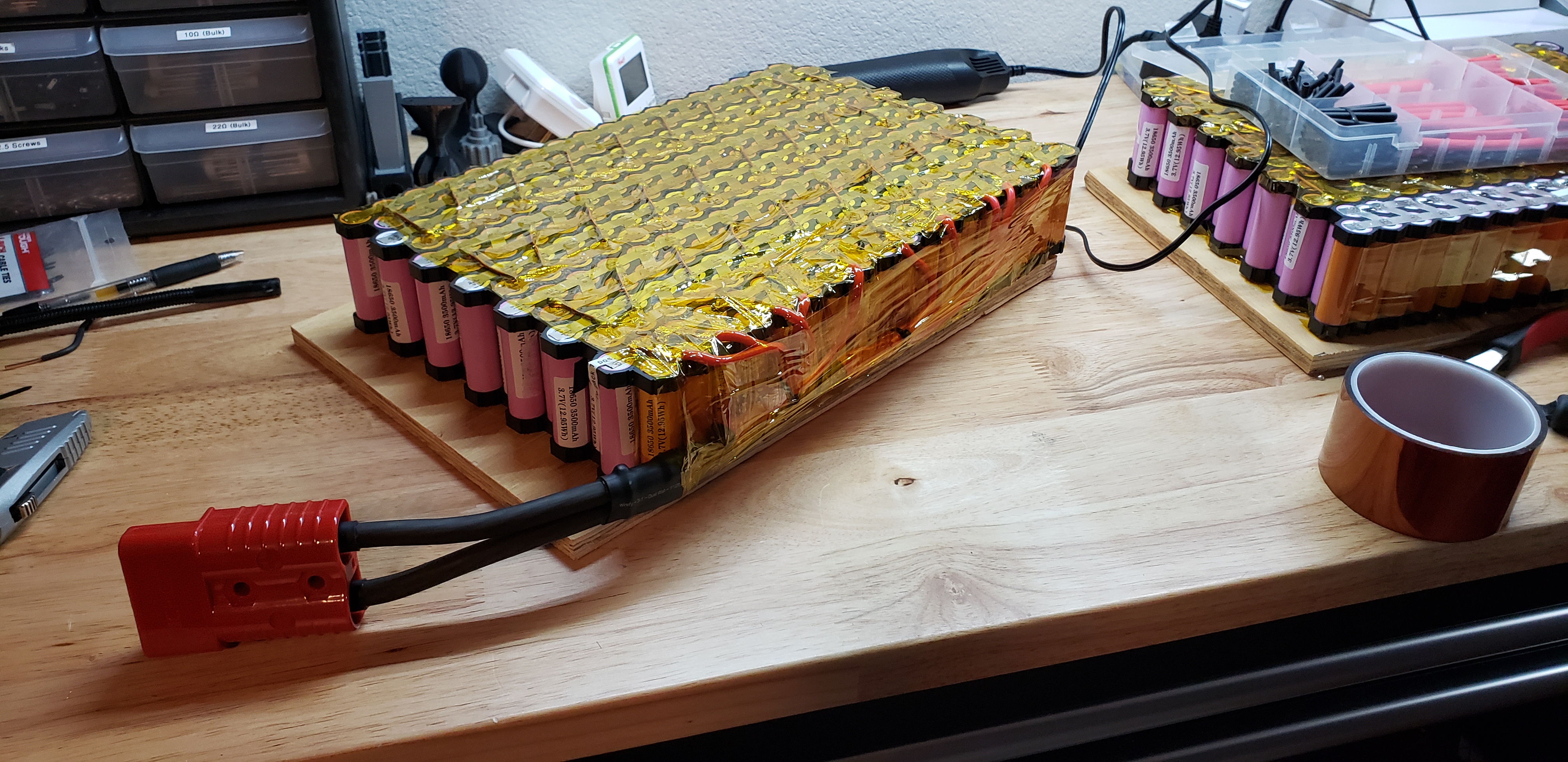
Hi, I'm building a 36P 14S portable battery using brand new Samsung INR18650-35E cells, and I would really like some help with brainstorming on how I can move forward from where I got stuck. This portable build is my first and I am taking it on as a learning experience, and as a precursor to eventually constructing my own home battery system.
I am specifically looking for feedback in regards to item #2 from the "potential solutions" section below, but I welcome any and all feedback!
Project Goals
I want to have the ability to draw up to 30A @ 120V continuously from a portable battery that I can take camping and use to power my home in an emergency situation. I have a 3.5kW continuous/7kW peak 120V AC inverter. My use cases should never draw 30A for any meaningful amount of time, and I don't plan to actually put a 30A load on the battery, but that is what I began designing it to realistically support. With a 30A load, this will draw roughly 86A from the DC side, including a worst case 15% inverter inefficiency loss, so each series connection needs to be able to support at least 86A continuous.
86A split up in a 36P array is roughly 2.4A per cell, or approximately 0.685C. I feel that while these low C rates for the cells will be good for them in the long run, I'm really limiting the instantaneous power I can get out of the battery. Therefore, I want to build the battery from the standpoint where I can simply upgrade the inverter in the future and support higher loads, so I'd like to over build the internal wiring. I would like to be able to support up to ~1.6C, or 5.59A per cell, or just over 200A for each parallel string in the pack.
So, I've shared how the battery will actually be used, but also shared the specifications that I want to build the battery to which will allow me to simply upgrade the inverter in the future to get a higher output.
The Problem..
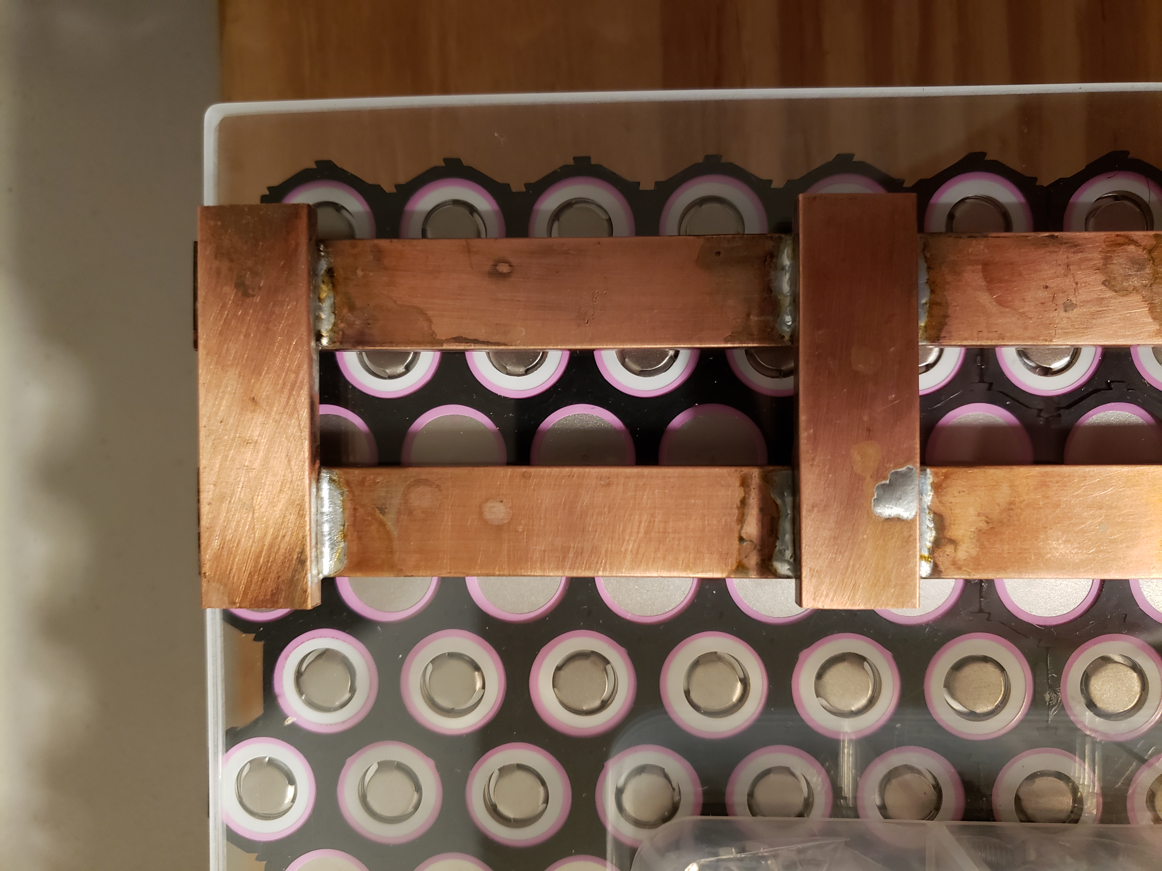
I had everything planned out and ran into some complications with the individual cell wiring during the build. The original plan was to wire each cell to a copper bus bar via 16AWG copper wire. Then, the series connections would consist of 5 short pieces of copper bus bar to bridge between the bars handling the parallel connections. Here's an example of the bus bars I cut and soldered - note that the copper wiring to connect each cell to the bar isn't shown. This is one bus bar assembly that connects the + side of a 36P string to the negative side of the adjacent 36P string.
The problem came up when I tried soldering copper wire onto the bus bar. The bars soak up too much heat, and I can't get them hot enough to melt the solder - even with my Weller 240W soldering gun. I soldered the bus bar assemblies with a torch, but obviously I can't do that on the pack itself!
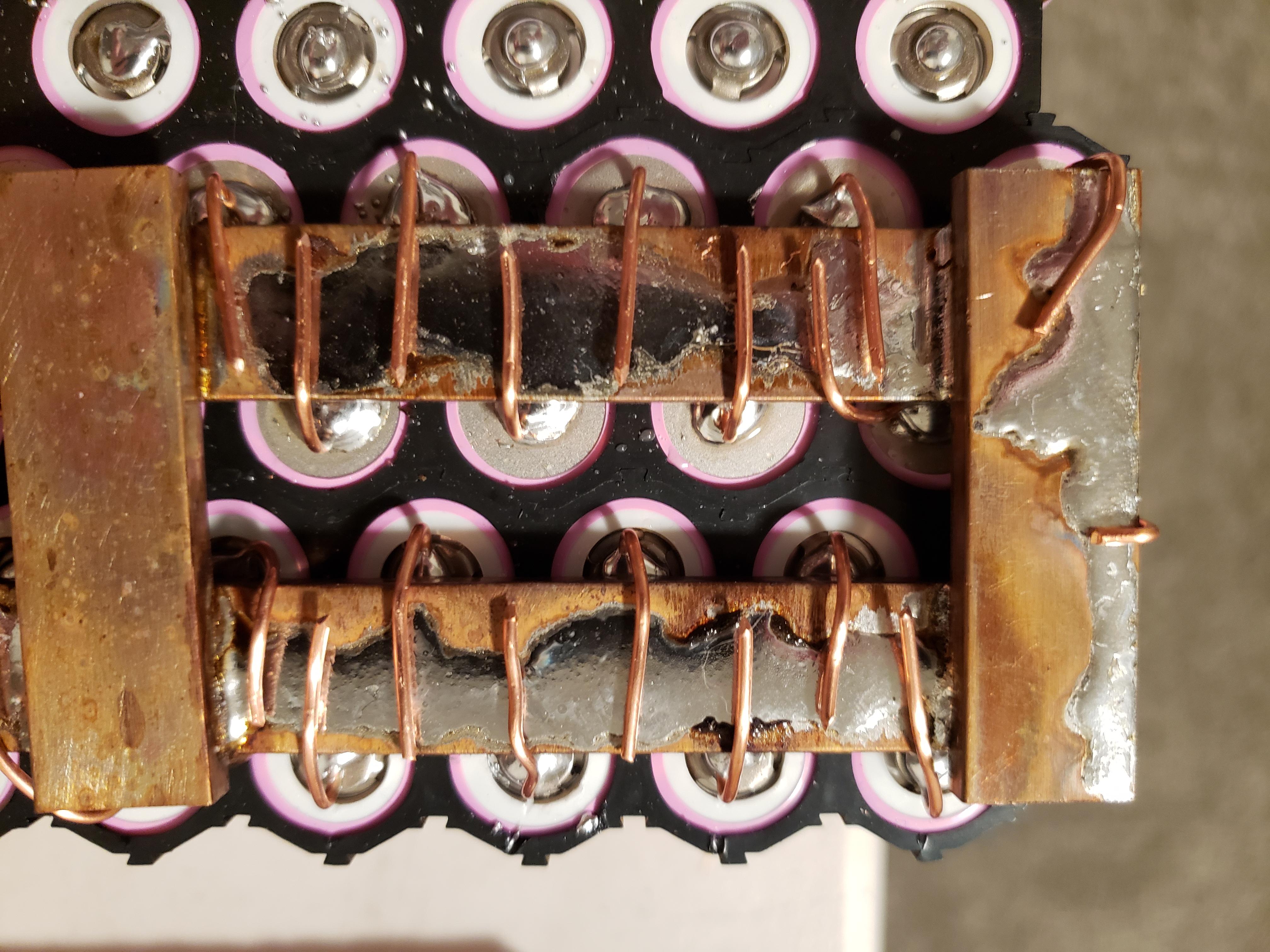
Specifically, the problem is attaching these wires to the copper bus bar. In this photo, I tinned the copper bus bar outside with my torch thinking it would help the solder melt with my soldering gun, but when I went to solder the wires onto the tinned copper, copper just disperses heat faster than my soldering gun can warm it.
Potential Solutions..
1) A friend of mind suggested that I drill and tap the copper bus bars and use another piece of copper bar to clamp the wires between. I'm not particularly fond of this idea because that is a LOT of drilling and tapping, but also because I would not be comfortable with a mechanical connection that could come lose over time as the pack warms and cools. Loctite may help ease that concern, but I think there are better solutions.
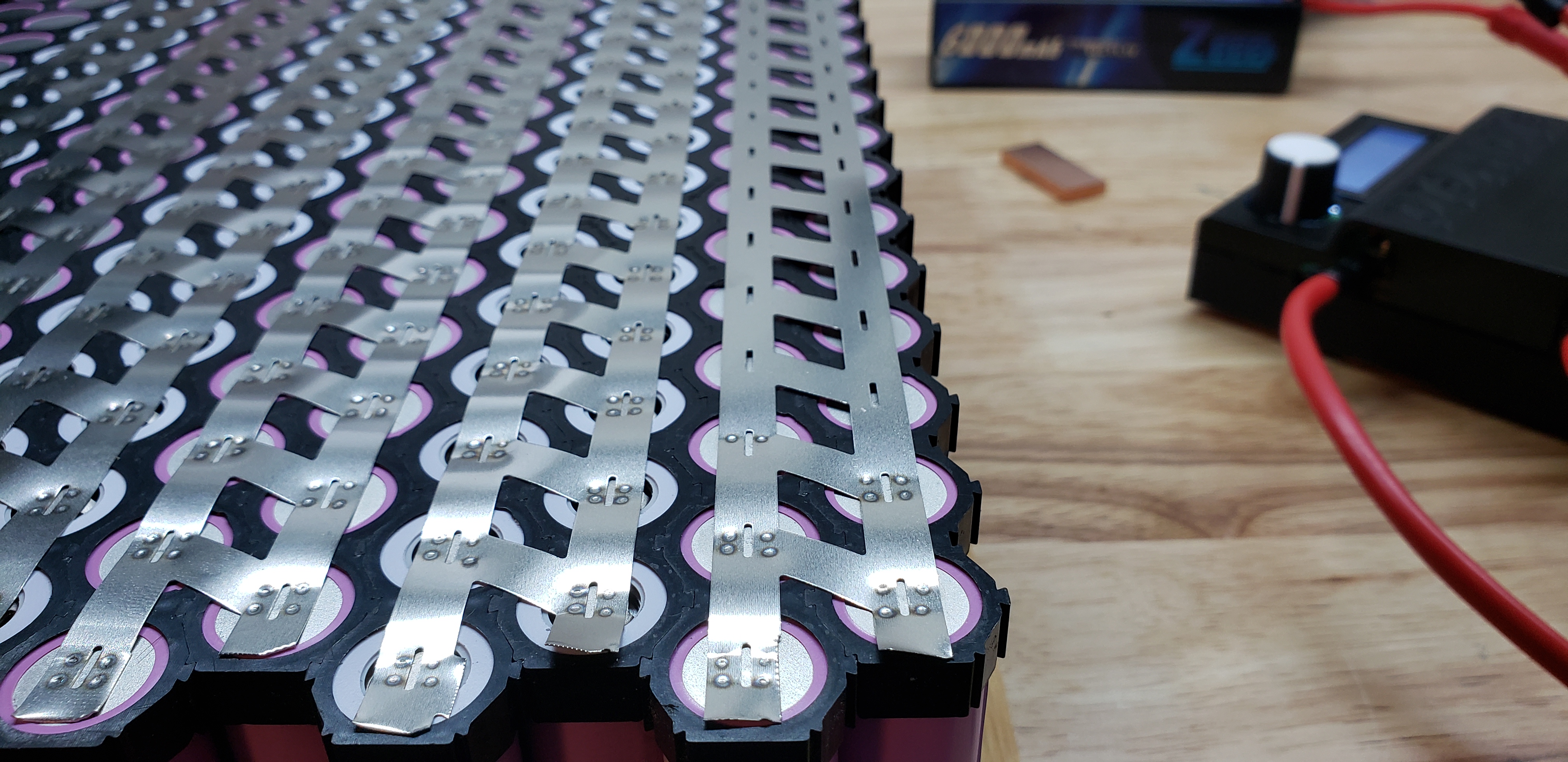
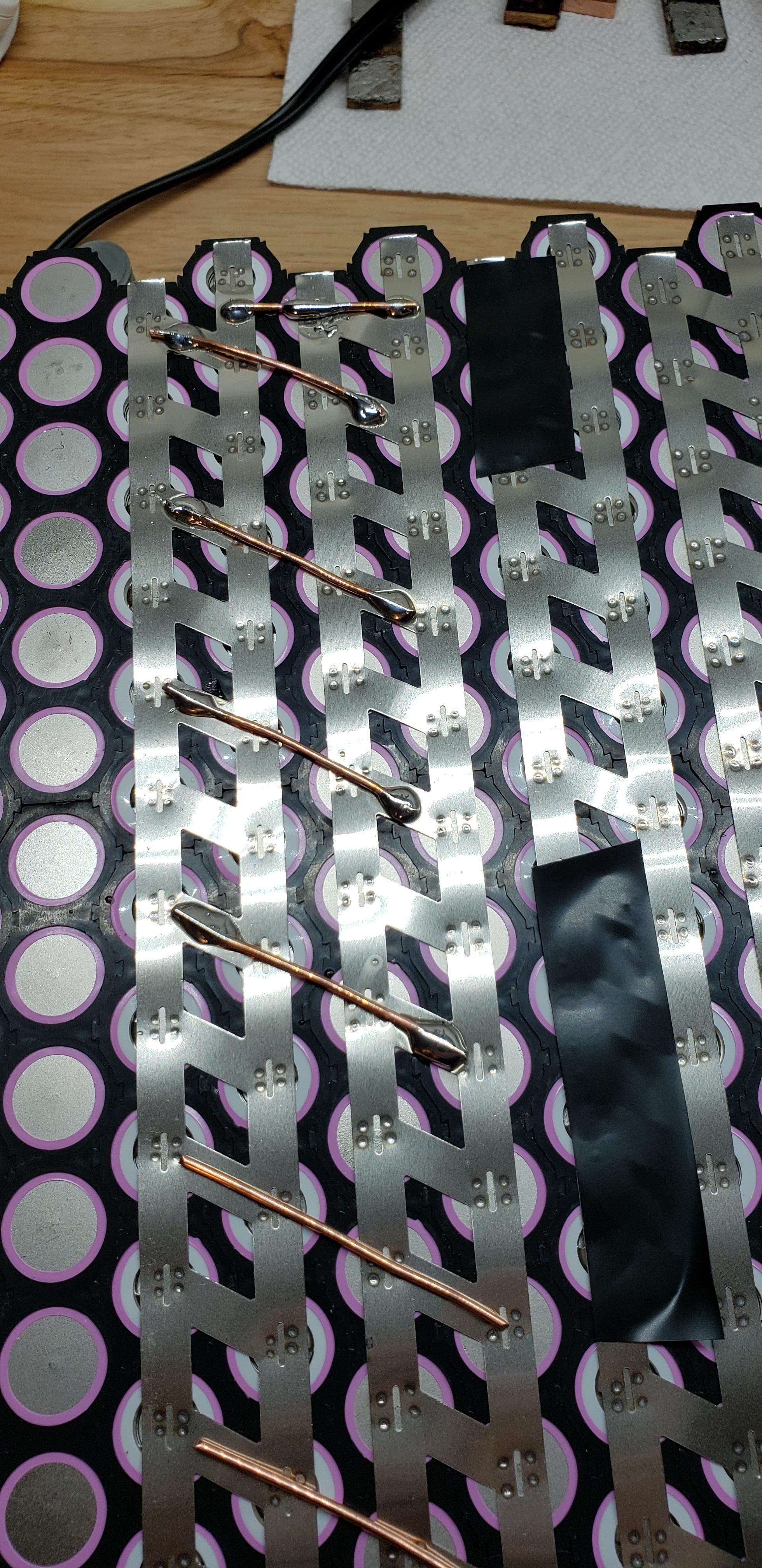
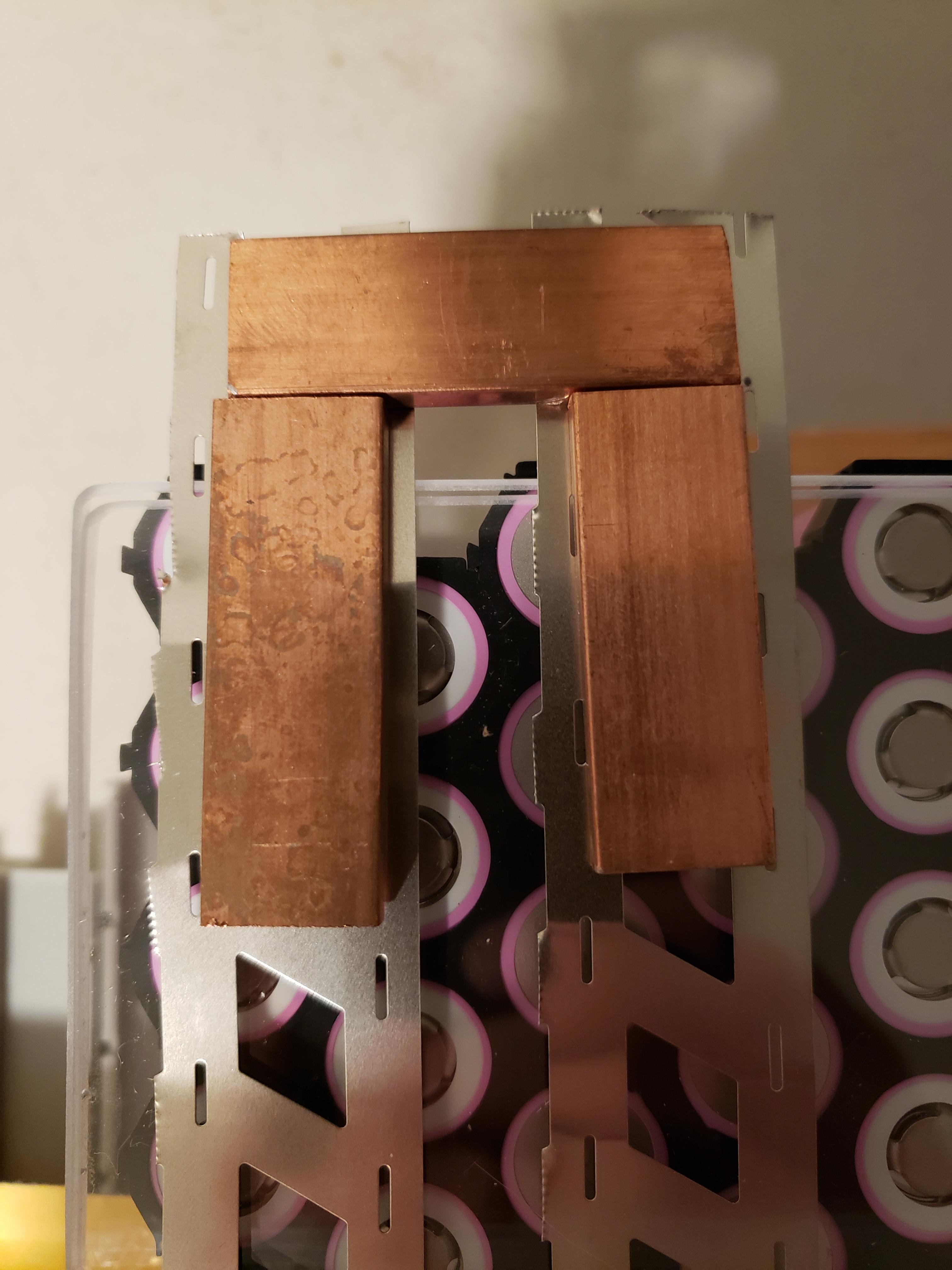
2) I revisited the idea of using nickel strip for the parallel connections. In my search for nickel strip ampacity, I came across this post where forum member spinningmagnets shared the idea of using what they call a "collector" at the end of the nickel strip. According to the ampacity charts in that same thread, I would be fine using a 0.2mm thick x 7mm wide nickel strip (or a 2P strip where 7mm is the smallest width). However, I'm unsure how the nickel strip would handle the current at the "collector" if there is upwards of 200A on a series connection. This is an example of what I'm thinking, with some spare 2P strip I had on hand and a scrap piece of my copper bus bar:
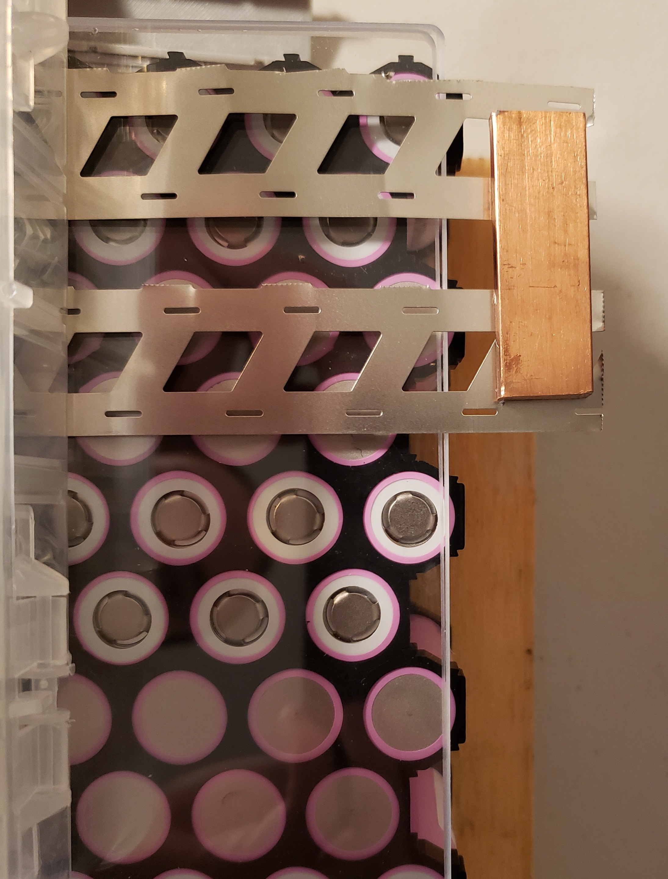
Wouldn't the small bit of nickel strip that is exposed between the copper bus bar and the first couple of cells also experience the full amount of current from the series connection? I understand that all members of a parallel group split the total system current evenly (well, in theory, anyways), and that a series connection will see the full amount of current. What I don't get with this collector idea is that if the full amount of current (say, 200A) travels through the bus bar link between the nickel strips, it surely doesn't just stop being 200A when it touches nickel! Wouldn't I need to add more copper to the serial connection, like this?
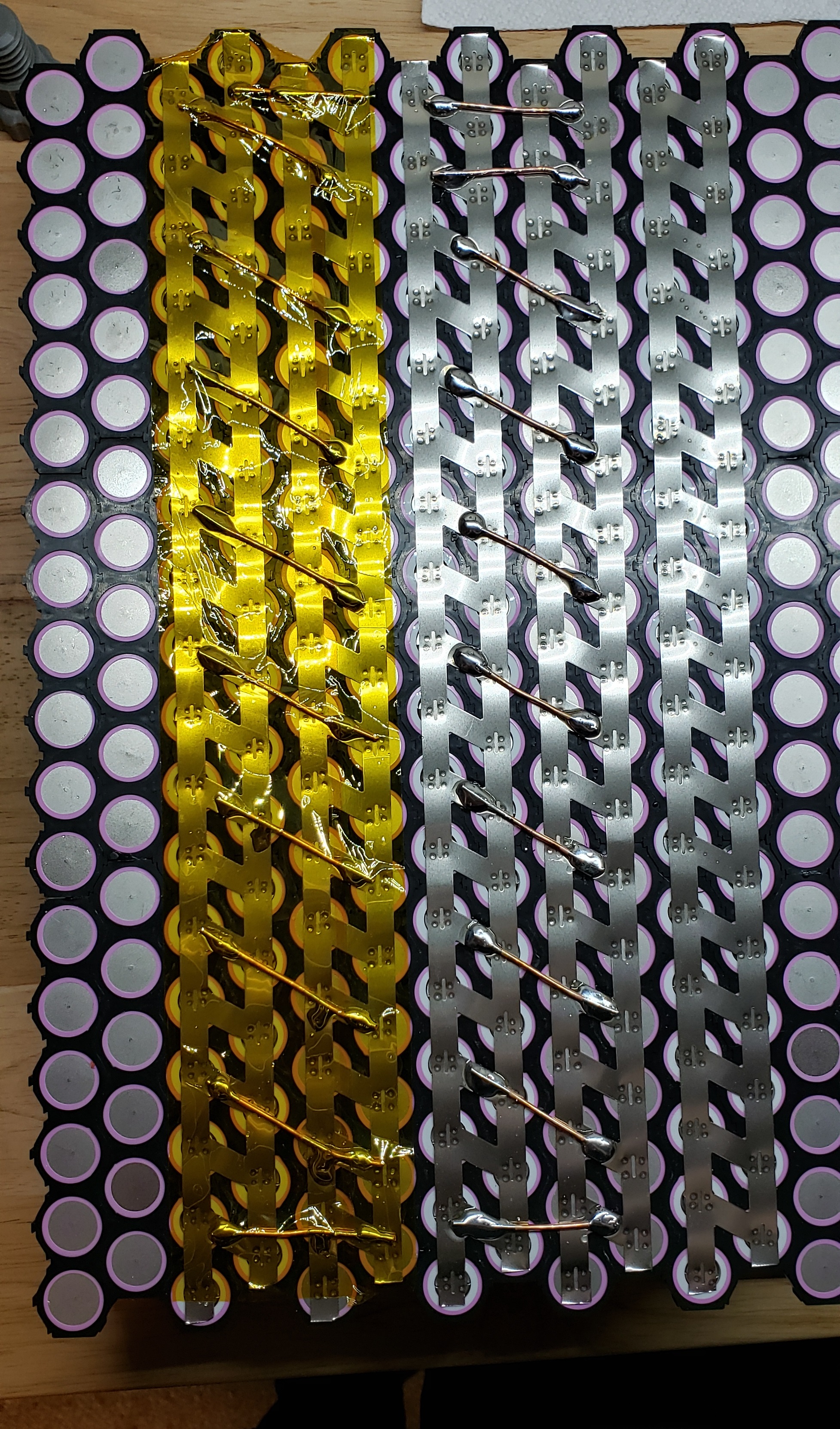
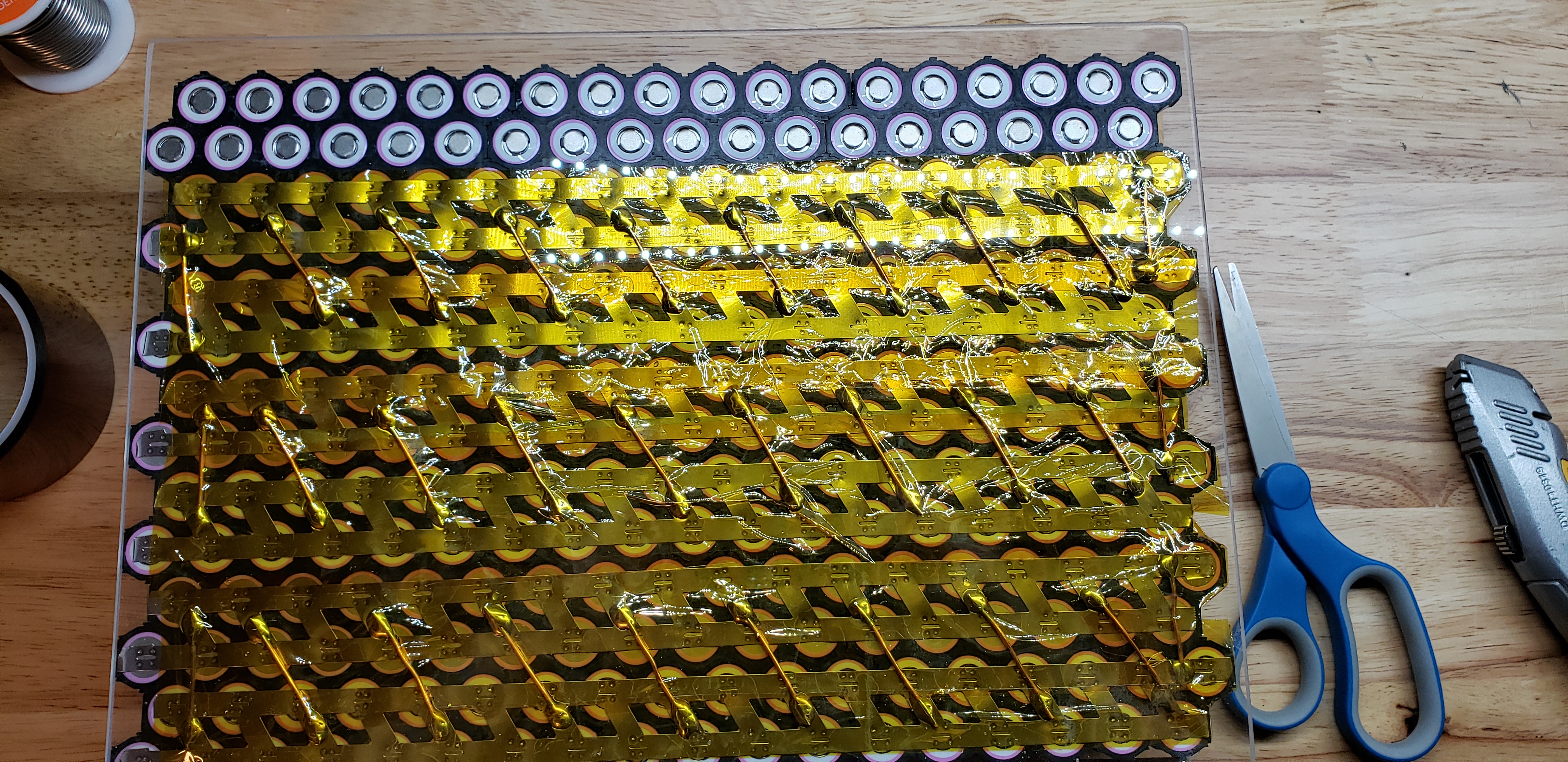
Or, could I add additional serial bridges between the nickel strip, like how I did with my original bus bar design?
Thanks so much for your time!
I am specifically looking for feedback in regards to item #2 from the "potential solutions" section below, but I welcome any and all feedback!
Project Goals
I want to have the ability to draw up to 30A @ 120V continuously from a portable battery that I can take camping and use to power my home in an emergency situation. I have a 3.5kW continuous/7kW peak 120V AC inverter. My use cases should never draw 30A for any meaningful amount of time, and I don't plan to actually put a 30A load on the battery, but that is what I began designing it to realistically support. With a 30A load, this will draw roughly 86A from the DC side, including a worst case 15% inverter inefficiency loss, so each series connection needs to be able to support at least 86A continuous.
86A split up in a 36P array is roughly 2.4A per cell, or approximately 0.685C. I feel that while these low C rates for the cells will be good for them in the long run, I'm really limiting the instantaneous power I can get out of the battery. Therefore, I want to build the battery from the standpoint where I can simply upgrade the inverter in the future and support higher loads, so I'd like to over build the internal wiring. I would like to be able to support up to ~1.6C, or 5.59A per cell, or just over 200A for each parallel string in the pack.
So, I've shared how the battery will actually be used, but also shared the specifications that I want to build the battery to which will allow me to simply upgrade the inverter in the future to get a higher output.
The Problem..
I had everything planned out and ran into some complications with the individual cell wiring during the build. The original plan was to wire each cell to a copper bus bar via 16AWG copper wire. Then, the series connections would consist of 5 short pieces of copper bus bar to bridge between the bars handling the parallel connections. Here's an example of the bus bars I cut and soldered - note that the copper wiring to connect each cell to the bar isn't shown. This is one bus bar assembly that connects the + side of a 36P string to the negative side of the adjacent 36P string.

The problem came up when I tried soldering copper wire onto the bus bar. The bars soak up too much heat, and I can't get them hot enough to melt the solder - even with my Weller 240W soldering gun. I soldered the bus bar assemblies with a torch, but obviously I can't do that on the pack itself!
Specifically, the problem is attaching these wires to the copper bus bar. In this photo, I tinned the copper bus bar outside with my torch thinking it would help the solder melt with my soldering gun, but when I went to solder the wires onto the tinned copper, copper just disperses heat faster than my soldering gun can warm it.

Potential Solutions..
1) A friend of mind suggested that I drill and tap the copper bus bars and use another piece of copper bar to clamp the wires between. I'm not particularly fond of this idea because that is a LOT of drilling and tapping, but also because I would not be comfortable with a mechanical connection that could come lose over time as the pack warms and cools. Loctite may help ease that concern, but I think there are better solutions.
2) I revisited the idea of using nickel strip for the parallel connections. In my search for nickel strip ampacity, I came across this post where forum member spinningmagnets shared the idea of using what they call a "collector" at the end of the nickel strip. According to the ampacity charts in that same thread, I would be fine using a 0.2mm thick x 7mm wide nickel strip (or a 2P strip where 7mm is the smallest width). However, I'm unsure how the nickel strip would handle the current at the "collector" if there is upwards of 200A on a series connection. This is an example of what I'm thinking, with some spare 2P strip I had on hand and a scrap piece of my copper bus bar:

Wouldn't the small bit of nickel strip that is exposed between the copper bus bar and the first couple of cells also experience the full amount of current from the series connection? I understand that all members of a parallel group split the total system current evenly (well, in theory, anyways), and that a series connection will see the full amount of current. What I don't get with this collector idea is that if the full amount of current (say, 200A) travels through the bus bar link between the nickel strips, it surely doesn't just stop being 200A when it touches nickel! Wouldn't I need to add more copper to the serial connection, like this?

Or, could I add additional serial bridges between the nickel strip, like how I did with my original bus bar design?
Thanks so much for your time!


